Advertisement
Advertisement
Table of Contents

Related Manuals for Gree XE7C-24/HC


Summary of Contents for Gree XE7C-24/HC
- Page 1 Owner's Manual Original Instructions Wired Controller XE7C-24/HC Wired Controller XE7C-24/H GREE+...
- Page 2 To Users Thank you for selecting Gree product. Please read this instruction manual carefully before installing and using the product, so as to master and correctly use the product. In order to guide you to correctly install and use our product and achieve expected...
- Page 3 This marking indicates that this product should not be disposed with other household wastes throughout the EU. To prevent possible harm to the environment human health from uncontrolled waste disposal, recycle it responsibly to promote the sustainable reuse of material resources.
- Page 4 Contents 1 Safety Notices (Please be sure to abide them) ..1 2 Operation Notices............1 3 Display ................ 3 3.1 LCD of Wired Controller ........4 3.2 LCD Display Instruction ........4 3.3 Instruction of Status Column Icons ....... 5 4 Button .................
- Page 5 6.1 ON/OFF .............. 30 6.2 Mode Setting ............31 6.3 Temperature Setting ........... 32 6.4 Fan Setting ............34 6.5 Swing Setting ............. 35 6.6 Function Setting ..........36 6.7 Universal Setting ..........54 6.8 Timer Setting ............58 7 Error Display ............64 7.1 Table of Error Codes for VRF and Big Duct Unit 65 7.2 Table of Display Codes for U-Match Unit ....
- Page 6 Owner’s Manual 1 Safety Notices (Please be sure to abide them) WARNING: If not abide them strictly, it may cause severe damage to the unit or the people. NOTE: If not abide them strictly, it may cause slight or medium damage to the unit or the people.
- Page 7 Owner’s Manual When two wired controllers control one (or more) indoor unit(s), the address of wired controller should be different. Functions with “*” are optional for indoor units. If a function is not included in an indoor unit, wired controller can’t set the function, or setting of this function is invalid to the indoor unit.
- Page 8 Owner’s Manual system operation mode after voting. System mode priority defaults to master-slave mode, and only certain units have other system mode priorities. Hereby, Our company, declares that this product is in compliance with the essential requirement and other relevant provisions of RE Directive 2014/53/EU.
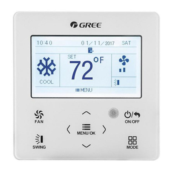
- Page 9 Owner’s Manual 3.1 LCD of Wired Controller Fig. 3.2 LCD graphics of wired controller 3.2 LCD Display Instruction Table 3.1 LCD display instruction Name Instruction Status column Display the icon of function that is turned on Fan speed It is for displaying the fan speed Swing It is for displaying the current swing status Display the function of menu/ok button at the...
- Page 10 Owner’s Manual Name Instruction It display the date and the time. When it’s Clock display locating the indoor unit, it displays the project No. of current indoor unit. NOTE: When wired controller is connected with different indoor units, some functions will be different. 3.3 Instruction of Status Column Icons Table 3.2 Instruction of Status Column Icon Symbols...
- Page 11 Owner’s Manual Symbols Name Instructions Absence is displayed when this Absence function is turned on. Quiet status (including quiet and auto Quiet status quiet modes) Energy- Energy-saving status of indoor unit saving Shield Shielding status Slave wired Slave wired controller (address of controller wired controller is 02).
- Page 12 Owner’s Manual Symbols Name Instructions Auto clean * Auto clean status I-DEMAND function, Indoor unit I-DEMAND* optional function. DRED* DRED gear control status Setback Setback function status NOTE: When wired controller is connected with different indoor units, some functions will be different. 4 Button 4.1 Button Silk Screen Fig.
- Page 13 Owner’s Manual 4.2 Buttons Function Instruction Table 4.1 Buttons function instruction Name Function Switch fan speeds: auto, low, medium-low, medium, Medium-high and high (1) Set operation temperature for the indoor unit. (2) Move cursor. (3) Set and check parameters. On/off button for turn on or turn off the unit; back button for return to previous page.
- Page 14 Owner’s Manual 5 Installation and Commissioning Unit: mm Fig. 5.1 Dimension of Wired Controller Fig. 5.2 Parts and Components of Wired Controller...
- Page 15 Owner’s Manual Panel of Soleplate Self-tapping screw Screw Name wired of wired ST3.9×25 MA M4×25 controller controller 5.1 Instruction of Wired Controller 5.1.1 Requirements for Model Selection of Communication Wire Fig. 5.3 Length of communication wire...
- Page 16 Owner’s Manual Wire Total Wire size Material material length L Remarks standard type (m/feet) (1) Total length of communication line can't exceed 250m (820- Light/ Ordinary 1/5feet). 2×0.75 Polyvinyl (2) The cord shall be ~2× chloride L≤250m circular cord (the 1.25 mm sheathed (L≤820-...
- Page 17 Owner’s Manual 5.1.3 Requirements for Wired Connection Network connecting methods between wired controller and indoor unit are as below: Fig. 5.4 One wired controller controls one indoor unit...
- Page 18 Owner’s Manual Fig. 5.5 One wired controller controls multiple VRF indoor units simultaneously Fig. 5.6 One wired controller controls multiple U-Match simultaneously...
- Page 19 Please refer to 5.2.2 Parameter Setting. The terminal of the wire controller is non-polarized and cannot be connected to strong electric. NOTE: Wired controller XE7C-24/HC only supports one (or more) indoor unit(s) controlled by one wired controller.
- Page 20 Owner’s Manual 5.1.4 Installation Fig. 5.7 Installation of Wired Controller...
- Page 21 Owner’s Manual Fig. 5.7 shows a simple installation course of wired controller, and the following points should be noted: Before installation, please cut off the power supply of indoor unit, it is not allowed to operate with power supply; Pull out the 2-core twisted pair inside the installation hole in the wall, and thread the wire through the hole in the back of soleplate of wired controller;...
- Page 22 Owner’s Manual View and locate indoor unit project No. Select “IDU Project No. View and Locating” on the view page to go to indoor unit project No. view and locating page shown as below. Indoor unit project No. and error codes will be displayed on this page. If there are multiple indoor units, press “◀”...
- Page 23 Owner’s Manual After entering indoor unit project No. View and locating page, the buzzer of selected indoor unit gives out sound until exit from the view page or switch to the next indoor unit. One button to view all indoor units’ project No. (only for VRF unit) Select “View All IDU Project No.”...
- Page 24 Owner’s Manual Parameter View Select “parameter view” at the view page to enter into paremeter view page shown as below. As for the parameters, please refer to table 5.1 “Unit parameters view list”. When viewing the indoor unit, if there are multiple indoor unit, press “◀”...
- Page 25 Owner’s Manual press “◀” or “▶” button to switch outdoor units. Corresponding outdoor unit’s parameters will be displayed on the page. See the figure as below: Table 5.1 Unit parameters view list Parameter Parameter Range Range Name Name Wired Controller’s Number of IDUs 1~16 Address...
- Page 26 Owner’s Manual Parameter Parameter Range Range Name Name Relative Indoor Temp -30°C -139°C 0%~100% Humidity / RH Inlet Temp 1 -30°C -139°C Outlet Temp 1 -30°C -139°C Inlet Temp 2* -30°C -139°C Outlet Temp 2* -30°C -139°C IDU capacity IDU Capacity and capacity IDU EXV Status 0~20...
- Page 27 Owner’s Manual The following parameters can only be viewed from the master wired controller, they cannot be viewed from the slave wired controller Parameter Parameter Range Range Name Name Comp 4 Comp 3 -30~150°C Discharge -30~150°C Discharge Temp Temp. Comp 6 Comp 5 -30~150°C Discharge...
- Page 28 Owner’s Manual the set page to go into parameter setting page. See the figure as below. Select user parameter, project parameter and U-Match parameter to enter into corresponding parameter setting. See the figure as below: After that, press “ ” or “ ”...
- Page 29 Owner’s Manual items. If the setting can’t be confirmed, switching the item can restore the previous setting value. Please refer to table 5.2 for the settable parameters. Table 5.2 Unit’s parameters setting list Item Settable range Default Remarks When it is set as no, this wired controller is slave wired controller.
- Page 30 Owner’s Manual Item Settable range Default Remarks Once it is activated, the current IDU is set to be the master IDU. When the setting is Yes, if the system mode priority is the master-slave mode, the status column in Master IDU Yes, No homepage will display the icon of master IDU “...
- Page 31 Owner’s Manual Item Settable range Default Remarks After setting the linkage function, the fresh air IDU will automatically turn on or turn Link with off along with the on and off of Fresh Air Yes, No general IDU. Meanwhile, IDU* users can manually turn on or turn off the unit.
- Page 32 Owner’s Manual Item Settable range Default Remarks If select “yes”, set humidity is Yes: Humidity displayed under dry mode. Dry Mode control Otherwise, set temperature is Humidity No: Temperature displayed. It can only be set Control when it’s supported by the control indoor unit.
- Page 33 Owner’s Manual Item Settable range Default Remarks When it is set as No, it will Resume keep the status after inserting After the gate control card. If it is at Yes, No Inserting OFF status when pulling out Card the card, when inserting the card, it is still at OFF status.
- Page 34 – temperature lower limit ≥ 4°C; Lower When temperature unit is °F, 16~26°C 20°C Temp Limit temperature upper limit – (61~79°F) (68°F) of Setback temperature lower limit ≥7°F. Reset G- Only applicable to Wired Yes, No Cloud Controller XE7C-24/HC.
- Page 35 Owner’s Manual Item Settable range Default Remarks Occupancy Energy- Only applicable after installing -40~40 saving Smart Sensor. Time of I SENSE NOTES: ① Except for the above parameters, setting interface for other parameter can only be accessed by inputting password. ②...
- Page 36 Owner’s Manual Fig. 6.1 ON interface Fig. 6.2 OFF interface 6.2 Mode Setting Under On status, pressing “MODE” button can set modes circularly:...
- Page 37 Owner’s Manual NOTES: ① The available modes are different for different models. The wired controller will automatically select mode setting range according to the model of indoor unit. ② When the wired controller controls VRF unit and the system mode priority is the master-slave mode, only the master indoor unit can set the auto mode.
- Page 38 Owner’s Manual unit with this function. Please refer to 5.2.2 Parameter Setting for the setting method. NOTES: ① Only when the wired controller controls U-Match indoor units, the setting temperature can be adjusted by pressing “ ” or “ ” ▼...
- Page 39 Owner’s Manual 6.4 Fan Setting Under On status, pressing “FAN” button can set fan speeds circularly as: NOTES: ① Under Dry mode, fan speed is low and can’t be adjusted. ② When the wired controller is connected with a Fresh Air Indoor...
- Page 40 Owner’s Manual Unit, fan speed of indoor unit will be high fan speed only. Fan speed of indoor unit can’t be adjusted via “FAN” button. ③ If indoor unit’s fan speed is set auto, indoor unit will change fan speed automatically according to room temperature in order to make the room temperature more stable and comfortable.
- Page 41 Owner’s Manual into swing setting, and then press “◀” and “▶” button to switch to the left&right swing setting: 1)When the simple swing is set, press “Swing” button to turn on or turn off the left&right swing. 2)When the fixed-angle swing is set, press “Swing” button to switch swing statuses circularly as below: 6.6 Function Setting Press “Menu/OK”...
- Page 42 Owner’s Manual Some functions are with more parameters and “Menu/OK” button can be used for setting detailed parameters. Fig. 6.4 Function with detailed setting As for some functions, only the on/off status is displayed at the switch button. It needs to press “Menu/OK” button to enter into detailed setting: Fig.
- Page 43 Owner’s Manual 6.6.1 Turbo Setting Turbo fan Function: Turn on the highest fan speed, and then turbo fan will be displayed on the homepage. Turn on turbo fan Function: Under on status, select turbo fan on the function page and press “◀” or “▶” button to turn on or turn off the turbo fan.
- Page 44 Owner’s Manual Cancel air function: Same as the method used for turning on the air function. When selecting the air function on the function page, press “Menu/OK” button to go air level setting. The display is as below: Fig. 6.6 Air level setting Press “...
- Page 45 Owner’s Manual Level of Air setting Opening time Always of fresh air valve NOTE: Time indicated in the table: unit’s operating time (min) / opening time of fresh air valve per operating time (min). 6.6.3 Sleep Setting Sleep Function: The unit will operate according to the preset sleep curve to provide comfortable sleep environment.
- Page 46 Owner’s Manual the health function. 6.6.5 I-Demand Setting* I-DEMAND function: The unit operates in the SE mode to save energy. I-DEMAND function can only be used under cooling mode. Turn on I-Demand function: When the unit is turned on, under cooling mode, select I-Demand on the function page, and then press “◀”...
- Page 47 Owner’s Manual Turn on save mode: Under on status, select save function on the function page and press “◀” or “▶” button to turn on or turn off the save function. Cancel save mode: Same as the method used for turning on the save function.
- Page 48 Owner’s Manual NOTE: When the save function is turned on and then set temperature exceeds the limit value for save function, “ ” icon blinks three times and then buzzer will give out two sounds successively. 6.6.8 X-FAN Setting X-fan function: If the unit is turned off under Cooling or Dry mode, the evaporator of indoor unit will be dried off automatically to prevent bacteria and mould from gathering.
- Page 49 Owner’s Manual Fig 6.8 Filter clean reminder setting Press “ ” or “ ”button to switch items. When selecting the first ▼ ▲ item, press “◀” or “▶” button to turn on or turn off this function; when selecting the second item, press “◀” or “▶” button to switch current environmental cleanliness (switch among level 1, level 2 and level 3.
- Page 50 Owner’s Manual button, the accumulated time will increase 400h. When the time exceeds the maximum value, it will turn back to the minimum value. Serious pollution: When current cleanliness is “3”, the setting range for the clean cycle is 100h-1000h. After each pressing of “▶” button, the accumulated time will increase 100h.
- Page 51 Owner’s Manual Fig. 6.9 Quiet mode setting Press“ ”or “ ” button can adjust the quiet mode (quiet mode and ▼ ▲ auto quiet mode). Press “Menu/OK” button to save the setting. NOTES: ① When quiet function is enabled, indoor unit will operate at quiet fan speed.
- Page 52 Owner’s Manual and then press “◀” or “▶” button to turn it on or turn it off. Cancel low-temperature dry function: Same as the method of turning on the low-temperature dry function. 6.6.12 Setback Function In unit off status with setback function activated, the unit will operate in heating mode automatically when indoor temperature is lower than temperature lower limit for setback function and operate in cooling mode automatically when indoor temperature is higher than...
- Page 53 Owner’s Manual Set setback temperature: Setback Upper Temp Limit: select “Upper Temp Limit of Setback” on the user parameters page, and press “◀” or “▶” button to adjust the upper temperature limit of setback function. Press “Menu/OK” button to save the setting. Setback Lower Temp Limit: select “Lower Temp Limit of Setback”...
- Page 54 Owner’s Manual function can be turned on under cooling, heating, auto and dry modes. Turn on DRED function: Under on status, select DRED on the function page and then press “◀” or “▶” button to turn on or turn off DRED function.
- Page 55 Owner’s Manual on the independent swing function. When turning on the independent swing, select the independent swing on the function page and press “Menu/OK: button to go to the independent swing setting. The display is as below: Fig 6.11 Independent swing setting Press “...
- Page 56 Owner’s Manual ③ As for the independent swing, one air outlet at the most can be set closed. When the air outlet is closed, it can’t supply the air outlet. ④ Turning off the independent swing can restore to the original up&down swing setting.
- Page 57 Owner’s Manual NOTES: ① This function is only applicable to the unit with auto clean function. ② When the unit is faulty, auto clean function cannot be turned on. ③ When auto clean function is turned on, there will be some phenomenons, such as frosting of evaporator of indoor unit, sound of liquid flow, and fluctuation of indoor temperature and humidity, which will affect the comfort.
- Page 58 Owner’s Manual When the remote monitor or central controller activates remote shield on the wired controller, icon “ ” will show. If user wants to control it through the wired controller, icon “ ” will blink to remind that these controls are disabled. 6.6.17 Gate-Control Function When there is gate-control system, user can insert a card to turn on the unit or pull off a card to turn off the unit.
- Page 59 Owner’s Manual Turn on I-SENSE function: Turn on the unit, when it is in cooling or heating mode, select I-SENSE in the function page, and then press “◀” or “▶” to turn on or turn off I-SENSE function. Cancel I-SENSE: Same as the method used for turning on I- SENSE function.
- Page 60 6.7.1 WiFi Function Setting "GREE+" App can be used to control wired controller XE7C- 24/HC. Please scan the QR code or search "GREE+" in the application market to download and install it. When "GREE+" App is installed, register the account and add the device to achieve long- distance control and LAN control of Gree smart home appliances.
- Page 61 0.5s, WiFi resetting is succeeded. After that, add devices to the App. NOTES: ① This function is only applicable to wired controller XE7C-24/HC. ② If the device is offline or router’s name and password have been changed, please reset WiFi and add the device again.
- Page 62 Owner’s Manual 6.7.2 Time Format Setting Users can set 12-hour time format or 24-hour time format. Press “ ” or “ ”button on the setting page to select “time format” and then ▼ ▲ press “◀” or “▶” button to select 12-hour time format or 24-hour time format.
- Page 63 Owner’s Manual 6.7.5 Temperature Unit Setting Users can set the temperature unit on the wired controller as °C or℉. Press “ ” or “ ”button to select “In℉” on the setting page; press ▼ ▲ “◀” or “▶” button to select whether use℉. If not, the temperature unit on the wired controller will switch to °C.
- Page 64 Owner’s Manual Fig. 6.17 Timer setting page 6.8.1 Daily Timer Setting As for the daily timer setting, users can set four independent timer periods. Only when the timer period is turned on, it is valid. As for each timer period, it can set time, on/off, working mode, set temperature and fan speed.
- Page 65 Owner’s Manual 6.8.2 Weekly Timer Setting Users can set the timer for each day in a week, and they can also set 4 timer periods for each day. The unit will execute corresponding timer setting on weekly basis circularly. When entering weekly timer setting page, press “◀”...
- Page 66 Owner’s Manual...
- Page 67 Owner’s Manual Fig. 6.19 Weekly timer setting When entering to weekly timer setting page, press “◀” or “▶” button to select the setting item, press “ ” or “ ”button to set the value ▼ ▲ and then press “Menu/OK” button to save the setting. 6.8.3 Two-week Timer Setting Users can set the timer for each day in two weeks and they can also set 4 timer periods for each day.
- Page 68 Owner’s Manual Fig. 6.20 Two-week timer menu Select the item of “two week schedule”, press “Menu/OK” button to enter into its setting page, select the item of “current week” and then press “◀” or “▶” button can set the current week as the first week or the second week.
- Page 69 Owner’s Manual every time, it will be turned off automatically after operation for “x” hours. When entering timer OFF page, press “ ” or “ ”button to set the ▼ ▲ time for timer OFF, set the time change at the interval of 0.5h and then press “Menu/OK”...
- Page 70 Owner’s Manual Fig.7.1shows the display of outdoor unit high pressure protection when unit is on. Fig. 7.1 Display of Outdoor Unit High Pressure Protection 7.1 Table of Error Codes for VRF and Big Duct Unit 7.1.1 Table of Error Codes for Outdoor Unit Error Error Code Content...
-
Page 71: Compressor
Owner’s Manual Error Error Code Content Content Code High Pressure Protection of Abnormal Protection Pressure Discharge Low Protection of Water Flow Temperature Protection Switch Low Pressure Protection of Low High- Protection pressure Excess Discharge Oil Return Pipe is Temperature Protection Blocked of Compressor Low Temperature... -
Page 72: Table Of Contents
Owner’s Manual Error Error Code Content Content Code Compressor 1 Subcooler Gas-out Discharge Temperature Temperature Sensor Error Sensor Error Compressor 2 Gas-liquid Separator Inlet Discharge Temperature Temperature Sensor Error Sensor Error Compressor 3 Gas-liquid Separator Discharge Temperature Outlet Temperature Sensor Error Sensor Error Compressor 4 Outdoor Humidity Sensor... -
Page 73: Sensor Error Compressor
Owner’s Manual Error Error Code Content Content Code High and Low Pressure Compressor 5 Current Sensors are Connected Sensor Error Inversely Compressor 6 Current Oil-return 2 Temperature Sensor Error Sensor Error Malfunction of DC Oil-return 3 Temperature motor Sensor Error Compressor 1 Top Oil-return 4 Temperature Temperature Sensor... - Page 74 Owner’s Manual Error Error Code Content Content Code Protection of Compressor Compressor 3 Over- Drive Board Module current Protection Reset Compressor 4 Over- Error of Fan Drive Board current Protection Compressor 5 Over- Malfunction of Fan Drive current Protection Board Compressor 6 Over- Protection of Fan Drive current Protection...
- Page 75 Owner’s Manual Error Error Code Content Content Code Outlet Pipe Temperature Mode Conflict Sensor 2 Error No Master Indoor Unit Middle Tube Temperature Error Sensor 2 Error Power Insufficiency Fresh Air Inflow Protection Temperature Sensor Error Quantity Of Group Indoor Air Box Sensor Control Indoor Units Error Setting Error...
- Page 76 Owner’s Manual Error Error Code Content Content Code Inconsistency of Group- controlled Indoor Units in Reheat Motor Drive Error Dehumidification System Low Voltage of IDU Bus Indoor Fan 2 Error Lift Panel Return Air High Voltage of IDU Bus Frame Reset Exception Indoor Unit PC-Board IDU IPM Module Error...
- Page 77 Owner’s Manual Error Error Code Content Content Code High Temperature of IDU Jumper Cap Error Module Indoor Unit Hardware IDU Charging Circuit Address Error Error Wired Controller PC- Temperature Sensor Error Board Error of IDU Module Capacity DIP Switch — —...
- Page 78 Owner’s Manual Error Error Code Content Content Code Communication error Wrong Address of between master control Compressor Drive and inverter fan motor Board drive Error of Lack of Indoor Valve Abnormal Alarm Unit Grid DRED0 Response Alarm of Indoor Unit Protection Project Number Collision Indoor Unit Tube...
- Page 79 Owner’s Manual Error Error Code Content Content Code Indoor Unit System addresses is Identification Error of incompatible Mode Exchanger PV module F0 Error of Multiple Master protection Wired Controller Protection shutdown Communication Error error of thermal storage between Indoor Unit and module Remote Receiver Electronic expansion...
- Page 80 Owner’s Manual 7.1.4 Table of Status Codes Error Error Code Content Content Code Unit is waiting for Shielding status debugging Check the compressor Compulsory defrosting operation parameters Setting of ordinary units After-sales Refrigerant and high sensible heat Reclaim units Select degree Celsius or Defrosting Fahrenheit Discharge low...
- Page 81 Owner’s Manual Error Error Code Content Content Code Setting of target degree Remote Urgent Stop of super-cooling of ODU PV grid-connected Emergency Stop settings Working mode of Operation Restriction compressor heating belt Lock status — — 7.2 Table of Display Codes for U-Match Unit 7.2.1 Table of Error Codes of Outdoor Unit Error Error Code...
- Page 82 Owner’s Manual Error Error Code Content Content Code Compressor Non- PFC Overcurrent Error synchronism Compressor High Voltage Protection Demagnetization of DC Bus Protection Low Voltage Protection Compressor Stalling of DC Bus Drive Board Startup Failure Communication Error Overcurrent of Drive Module Reset Compressor Phase Current Overspeed...
- Page 83 Owner’s Manual Error Error Code Content Content Code Sensor Connection Protection (current Outdoor Condenser sensor hasn’t been Outlet Pipe Temperature connected to Sensor Error corresponding U phase or V phase) Low Pressure Sensor Refrigerant Temperature Error Sensor Error Outdoor Pipe Middle ODU Refrigerant Heater Sensor Error Failure...
- Page 84 Owner’s Manual Error Error Code Content Content Code Compressor Suction Outdoor Condenser Temperature Sensor Middle Pipe Temperature Error Sensor Error Module Temperature 4-way Valve Sensor Circuit Error Commutation Error Zero-crossing Signal Abnormal Electrical Level Error of Selected Port Outdoor Ambient Memory Chip Read and Temperature Sensor Write Error...
- Page 85 Owner’s Manual Error Error Code Content Content Code IDU Water Full Inverter Indoor Fan Drive Protection Storage Chip Error Inverter Indoor Fan Drive IDU Jumper Cap Error Charging Circuit Error Inverter Indoor Fan Inverter Indoor Fan Drive Drive IPM Module AC Input Voltage Protection Abnormal Protection...
- Page 86 Owner’s Manual Error Error Code Content Content Code Wired Controller Inverter Indoor Fan Temperature Sensor Overcurrent Protection Error Inverter Indoor Fan Wired Controller Circuit Power Protection Board Error Group-controlled IDU Wired Controller Power Inconsistency of Reheat Supply Circuit Failure Dehumidification System Group-controlled IDU —...
Need help?
Do you have a question about the XE7C-24/HC and is the answer not in the manual?
Questions and answers