Table of Contents
Advertisement
Thank you for choosing Air Conditioners, please read this owner's manual carefully before operation
and retain it for future reference.If you have lost the Owner's Manual, please contact the local agent
or visit www.gree.com or send email to global@gree.com.cn for electronic version.
GREE reserves the right to interpret this manual which will be subject to any change due to product
improvement without further notice.
GREE Electric Appliances, Inc. of Zhuhai reserves the final right to interpret this manual.
User's Manual for Wired
Controller XK55
Advertisement
Table of Contents

Subscribe to Our Youtube Channel
Related Manuals for Gree XK55


Summary of Contents for Gree XK55
- Page 1 Owner’s Manual, please contact the local agent or visit www.gree.com or send email to global@gree.com.cn for electronic version. GREE reserves the right to interpret this manual which will be subject to any change due to product improvement without further notice.
- Page 2 User’s Notice The power supply method for all indoor units must be unified. Prohibit installing the wired controller at wet or sunshine places. Do not knock, throw or frequently disassemble the wired controller. Dot not operate the wired controller with wet hands. ...
-
Page 3: Table Of Contents
CONTENTS 1 Installation Instruction ............1 1.1 Selection requirement for communication wire ......2 1.2 Installation requirement ............. 3 1.3 Wiring requirement ..............4 1.4 Installation ................. 7 1.5 Disassembly ................8 2 Display Instruction ..............9 2.1 Outside view................9 2.2 Buttons instruction .............. - Page 4 5.3 Code table for debugging ............39 5.4 Code table for state ..............40 ...
-
Page 5: Installation Instruction
Wired Controller XK55 1 Installation Instruction Fig 1.1 Dimension of wired controller Fig 1.2 Wired controller parts... -
Page 6: Selection Requirement For Communication Wire
Wired Controller XK55 Panel of wired Soleplate of wire Terminal box installed in Name Screw M4X25 controller controller the wall Q’ty Provided by user 1.1 Selection requirement for communication wire Fig 1.3 Length of communication wire Total length of Wire... -
Page 7: Installation Requirement
Wired Controller XK55 Caution: ① If the air conditioner is installed the place with strong magnetic interference, the communication wire of wired controller must use shielding twisted pair wire. ② The communication wire of the wired controller must be selected according to this manual. -
Page 8: Wiring Requirement
Wired Controller XK55 1.3 Wiring requirement There are four kinds of wiring method for wired controller and indoor unit: Fig 1.4 One wired controller controls one Fig 1.5 Two wires controllers control one indoor unit indoor unit... - Page 9 Wired Controller XK55 Fig 1.6 One wired controller controls more indoor units simultaneously Fig 1.7 Two wired controllers control more indoor units simultaneously...
- Page 10 Wired Controller XK55 Wiring instruction: When one wired controller controls more indoor units at the same time, wired (1). controller can be connected to any one indoor unit and the connected indoor unit should be in the same series. The maximum quantity of indoor units controlled by the wired controller can’t exceed 16 sets and the connected indoor units should be in the...
-
Page 11: Installation
Wired Controller XK55 set. The quantity of wired controller can’t exceed two. Note: Series of indoor units include: ①Common Multi VRF Units; ②Fresh Air Units; ③ Double-heat Sources Units; ④ Combined Units; Except for fresh air units, double-heat sources units and combined units, the rest of indoor units belong to common multi VRF units. -
Page 12: Disassembly
Wired Controller XK55 Please pay attention to below items: Please disconnect the power support for indoor unit before installation. The (1). power must be disconnected during the whole installation process. Pull out the 2-core dual twisted pair wire from the installation hole on wall and (2). -
Page 13: Display Instruction
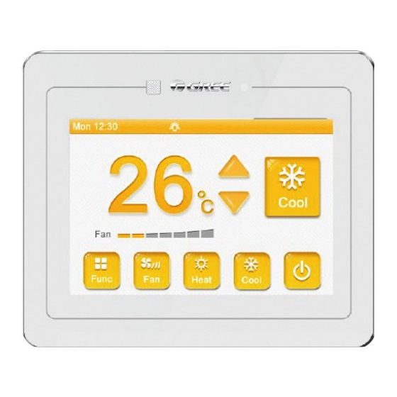
Wired Controller XK55 2 Display Instruction 2.1 Outside view Fig 2.1 Appearance of wired controller... -
Page 14: Buttons Instruction
Wired Controller XK55 2.2 Buttons instruction Fig 2.2 Button diagram... - Page 15 Wired Controller XK55 Button instruction Number Name Definition Receiving window of It’s used for receiving the signal of remote controller remote control signal ON/OFF Red color indicates the unit is off and white color indicates the indicator unit is on Temp button It’s used for adjusting operating temperature...
-
Page 16: Icon Instruction
Wired Controller XK55 2.3 Icon instruction Mode ( base on the indoor unit) Display Definition Display Definition Auto * Cooling Heating Floor heating * 3D heating * Space heating * Function, status Display Definition Display Definition Air * Gate-control Comfort(Reserved... -
Page 17: Operation Instruction
Wired Controller XK55 3 Operation Instruction 3.1 Summary This wired controller adopts 3.5 inch high-resolution lattice liquid crystal display, with capacitor type touch screen. Meanwhile, it’s with a slightly touch button used for turning on or turning off the unit, convenient for installation: Separation of function pages are realized for clear demonstration and high (1). -
Page 18: Page Instruction
Wired Controller XK55 3.2 Page instruction This wired controller is with clock time display function. For the first operation, if the system time is different from the current time. You can adjust the time on the setting page in order to ensure the accuracy of timer operation. Meanwhile, you can change backlight time, lightness, sound and language according to individual habit. - Page 19 Wired Controller XK55 After turning on the unit, press ▲ ▼ to adjust operating temperature and the temperature setting range is 16℃~30℃. Note: Under auto mode, the temperature adjust button is invalid. Press ON/OFF button to turn on or turn off the unit.
- Page 20 Wired Controller XK55 3.2.2 Function page Sleep function: Indoor unit will enter into sleeping operation status. It will operate according to the preset sleeping temperature curve to create comfortable sleeping ambient for improving sleeping quality. Absence function: Maintain indoor ambient temperature and keep the rapid heating after the unit is turned on.
- Page 21 Wired Controller XK55 When the unit is operating under cooling or heating mode, press Rapid to start up or turn off rapid function. After the unit is turned on under heating mode, press Absence to turn on or turn off absence function.
- Page 22 Wired Controller XK55 Quiet function: Reduce the noise of indoor unit. There are two kinds of mode for quiet function: quiet and auto quiet. Quiet function is not valid under auto, cooling, drying, fan, heating, 3D heating or space heating mode.
- Page 23 Wired Controller XK55 3.2.4 Air function page* Air function: Improve air quality through adjust indoor fresh air volume. Press ON to turn on or turn off the air function. Press ◀ ▶ to set the air grade.
- Page 24 Wired Controller XK55 3.2.5 Save function page Save function: Set temperature lower limit under cooling or drying mode or temperature upper limit for heating or 3D heating or space heating mode to let the air conditioner operate at appointed temperature range for saving energy.
- Page 25 Wired Controller XK55 3.2.6 Fix-angle swing page Fixed-angle swing function:It used for setting the swing position for up&down swing or left&right swing. Press U & D to switch up&down swing. Press L & R to switch left&right swing.
- Page 26 Wired Controller XK55 3.2.7 Filter cleaning page The prompting function for filter cleaning: The air conditioning unit can record its operation time. When it is at setting time, it will remind the user to clean filter so as to avoid filth blockage of filter without cleaning for a long time. The filth blockage of filter will lead to bad effect of cooling and heating function, abnormal protection and bacteria-collecting, etc.
- Page 27 Wired Controller XK55 Moderate pollution (B): when the cleaning frequency is “0”, it represents its (3). accumulative operation time is 1400 hours. For every “1” increases, the accumulative operation time adds 400 hours. When the cleaning frequency is “9”, the accumulative operation time is 5000 hours.
- Page 28 Wired Controller XK55 The timer can be set whenever the unit is turned on or turned off. Three weekly timers and one countdown timer can be chosen freely. In order to maintain the accuracy of time, please check the system time whether to be the current time before setting up timing.
- Page 29 Wired Controller XK55 Timer 1, 2, 3 is the weekly timer. We can set the mode, setting temperature, fan speed and repeat days when setting the function of timer on. If you want to set timer on/timer off, you can only have to activate the time of turn on/timer off; If you want the timer on and timer off are valid simultaneously, you can activate the time for timer on and timer off.
- Page 30 Wired Controller XK55 In this case, you can tick the days for repeat operation. 3.2.10 Time setting page...
- Page 31 Wired Controller XK55 It is used for setting hour and second individually and show the current value through the display so as to read conveniently. Click * Hour to set the accurate hour. Click * Minute to set the accurate minute.
- Page 32 Wired Controller XK55 3.2.12 Engineering setting page It is used for engineering debugging. Click the Master Wired Controller for turning up or turn off the master wired controller function. Click the Master IDU for turning up the indoor units function of main mode.
- Page 33 Wired Controller XK55 Introduction on each setting parameter Setting items Setting scope Acquiesce Remarks High Ceiling Turn on, turn turn off Only applicable to cassette units Installation If the power supply is not enough, we Turn on, turn permit giving priority on operation of...
- Page 34 Wired Controller XK55 Angle 1 Angle of Air Return Only applicable to units with Air Return Angle 2 Angle 1 Board Board. Angle 3 Automatic Automatic cooling: cooling: 17℃~30℃ 25℃ Cooling setting temperature - Heating Auto Temp setting temperature≥1. Automatic Automatic heating:...
- Page 35 Wired Controller XK55 Introduction for parameters view Parameter name Display scope Parameter name Display scope Number of IDUs 1~16 Filter Dirty Alarm Actual value cool only, heat Max Distribution 135%、150%、110% Cool & Heat Modes only, cool & heat, Ratio Wired Controller's 1、2...
- Page 36 Wired Controller XK55 Separator Outlet -30~139℃ -30~139℃ Oil Return Temp Temp ODU Heat EXV1 0~48 ODU Heat EXV2 0~48 Subcooler Liquid -30~139℃ Subcooler EXV 0~48 Temp Comp1 Operation ODU Fan Operation Freq 0~100Hz 0~200Hz Freq Comp3 Operation Comp2 Operation Freq...
-
Page 37: Special Function Explanation
Wired Controller XK55 3.2.13 View page It is used for displaying the current operation function so as to let you learn the units status at the first time. Press ∧ or ∨ to switch page. 4 Special function explanation 4.1 Remote shield function... -
Page 38: Entrance Guard Display Function
Wired Controller XK55 operation are invalid. When it is partial shield, the operation towards remote control of conductively-closed function of wired controller or button operation are invalid. When remote control or integrated controller is conducting remote shield towards wire controller, the main page status bar will display . When the user is conducting remote control or key button operation towards wire controller, it indicates the operation is invalid. -
Page 39: Abnormal Code
Wired Controller XK55 5 Abnormal code When there is any abnormalities occur during system operation, the main interface of wired controller will show multifunction icon , the specific code and indoor units located so as to let you understand the operation status of air conditioner at first time. - Page 40 Wired Controller XK55 Imperfect main Overcurrent Heat exchanger air board of outdoor protection of outlet temperature units compressor 3 sensor malfunction Overcurrent Oil return High pressure protection of temperature sensor malfunction compressor 4 sensor malfunction Overcurrent Low pressure Systematic hour...
- Page 41 Wired Controller XK55 Current sensor Protection Driver board abnormality of because high abnormality of compressor 1 pressure is too low compressor Supply voltage Current sensor Oil return pipe is protection of abnormality of blocked compressor driver compressor 2 board Restoration...
-
Page 42: Code Table For Indoor Unit Malfunction
Wired Controller XK55 5.2 Code table for indoor unit malfunction Code Content Code Content Code Content Inconsistent series Indoor unit of indoor units for Humidity sensor malfunction one controlling malfunction multiple units Indoor fan Severe turbidity of Water temperature protection... - Page 43 Wired Controller XK55 5.3 Code table for debugging Code Content Code Content Content Outdoor units High rating Capacity Invalid charge of capacity Code/Setting of refrigerant configuration jumper is wrong Dial-up error for Low rating Phase protection of emergent operation of...
- Page 44 Wired Controller XK55 5.4 Code table for state Code Content Code Content Long-distance stop operation Unit is on standby for debugging due to emergency Inquiry on operation parameter of Stop operation due to press emergency status Recovery operation of refrigerant...
- Page 45 GREE ELECTRIC APPLIANCES, INC. OF ZHUHAI Add: West Jinji Rd, Qianshan, Zhuhai, Guangdong, China, 519070 Tel: (+86-756) 8522218 Fax: (+86-756) 8669426 E-mail: gree@gree.com.cn www.gree.com ...
Need help?
Do you have a question about the XK55 and is the answer not in the manual?
Questions and answers