
Related Manuals for Oliver 0008


Summary of Contents for Oliver 0008
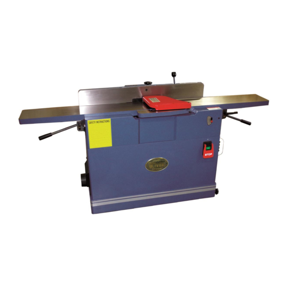
- Page 1 Model 0008 8” Jointer Owner’s Manual Oliver Machinery M-0008 02/2017 Copyright 2003-2017 Seattle, WA info@olivermachinery.net www.olivermachinery.net...
-
Page 2: Table Of Contents
Page Table of contents SAFETY INSTRUCTIONS ...................... 2 Unpacking and cleaning......................4 Placement the 8” jointer ......................4 Switch ............................. 5 Installation Blade Guard & Removal ..................5 Grounding Instructions ......................6 Adjustments ..........................7 Fence Adjustments: Tilt ....................... 10 Helical Cutterhead ........................ -
Page 3: Safety Instructions
SAFETY INSTRUCTIONS For Your Safety Read Instruction Manual Before Operating Jointer As with all machines, there is a certain amount of hazard involved with the use of this jointer. Use the machine with the respect and caution demanded where safety precautions are concerned. When normal safety precautions are overlooked or ignored, personal injury to the operator can result. - Page 4 Disconnect tools before servicing; when changing accessories, such as blades, bits, cutters, and the like. Reduce the risk of unintentional starting. Make sure switch is in off position before plugging in. Use recommended accessories. Consult the owner’s manual for recommended accessories. The use of improper accessories may cause risk of injury to persons.
-
Page 5: Unpacking And Cleaning
Unpacking and cleaning To ensure maximum performance from your 8" jointer, clean it properly; and install it accurately before use. As soon as you receive the jointer, we recommend you follow these procedures: 1. Finish removing the contents of the shipping carton and compare with the contents list. -
Page 6: Switch
Installation Blade Guard & Removal Switch The jointer is equipped with a push-button WARNING: The Jointer knives are extremely switch, Fig. 1 that will accept a safety padlock sharp. Use caution when working with or around (not included). the cutterhead. Use the jointer guard for all operations. -
Page 7: Grounding Instructions
Extension Cords Grounding Instructions Use proper extension cord. Make sure your WARNING: If the machine does not come ! extension cord is in good condition. When using wired to run, the electricals and motor an extension cord, be sure to use one heavy wiring must be done by a qualified enough to carry the current your product will electrician. -
Page 8: Adjustments
Adjustments Warning: Always disconnect the machine from OUTFEED INFEED the power source before making any TABLE (LEFT) TABLE (RIGHT) adjustments. Failure to heed this warning can lead to serious personal injury. To adjust outfeed table The outfeed table should be set level with the Fig. - Page 9 Depth of Cut Depth of cut is determined by the height of the infeed table relative to the high point of the knives on the cutterhead. When facing the width of a board (as opposed to the edge of a board), NEVER attempt to take off more than 1/64"...
- Page 10 5. Loosen the Hex. Nut (N) under the fence Table Leveling bracket (O), remove the fence assembly (P), The table level on your machine is factory FigFig. 16 adjusted and may never require readjustment. Should any adjustment become necessary, do the following: 1.
-
Page 11: Fence Adjustments: Tilt
Fence Adjustments: Tilt Fence Stop Adjustments Periodically check the 90° and 45° backward (135°) tilt accuracy of the fence with an angle Warning: Do not connect the plug to power measuring device, such as an adjustable source square or machinist’s protractor. Fence adjustments are made with the lock 0º... -
Page 12: Helical Cutterhead
45º & 135 º Fence Backward Stop Helical Cutterhead Adjustment Knife inserts are dangerously sharp. Use Referring to Fig. 22: extreme caution when inspecting, removing, or Note: The 45º fence backward stop is replacing knife inserts. controlled by the stop bolt (H) and 135 º fence backward stop is controlled by the stop bolt (I). -
Page 13: Cutterhead Removal
Step 5. Remove the V-belt (J) from cutterhead Cutterhead Removal pulley and motor pulley. If removal of the cutterhead is necessary, do the following: WARNING: Disconnect jointer from ! power source. Step1. Loosen 8 screws (B) on the rear cover by 4mm Hex. -
Page 14: Replacement
Step 9. Lower both of Infeed Table & Outfeed Replacement Table on the Lowest position (1/2”) Jointing Knives Infeed Table Outfeed Table After extended use it will be necessary to sharpen the knives on the cutterhead assembly so that all knives protrude exactly the same height above the cutterhead . -
Page 15: Replacement The Belts
Replacement the Belts After extended use it will be necessary to adjustment or change the belts on the jointer, do the following: WARNING: Disconnect machine from power source. Use approved eye ! protection whenever sharpening blades. 1. Loosen screws (A) & (B) then remove the pulley cover (C) &... -
Page 16: Basic Operations
two handed push Basic Operations block Before making any cuts on the stock, make a few practice cuts by raising the infeed table to “ 0" and with the power disconnected. In this manner you will acquaint yourself with the feel of jointer operations. - Page 17 Surfacing: Long Boards left hand pushes down toward fence as right hand The use of push blocks will help to insure starts feed against hands coming in contact with cutterhead in the event of a kickback and as trailing end of board passes over cutterhead.
- Page 18 Jointing (or Edging) Never edge a board that is less than 3 inches move fence forward wide, less than 1/4 inch thick, or 12 inches to expose only amount of cutterhead required long, without using a push block. CAUTION: When workpiece is twice the è...
-
Page 19: Push Blocks
Skewing (Shear Cutting) When edging or facing burl or birds-eye maple, it is not unusual to deface or mar the surface being finished. This is caused by the cutterhead blades at times cutting against the grain. In order to prevent the defacing or marring of this type wood, it is necessary to skew, or angle finish, the material being worked. -
Page 20: Wiring Diagrams
Wiring Diagrams... -
Page 21: Parts Diagrams
Parts Diagrams... -
Page 24: Parts List
Parts List Part No. Descriptions Q'ty 240080-904 KNOB 001902-109 SET LOCK SCREW M6*1.0P*6 010003-000 RETAINING RING STW-12 381336-901 SHAFT 250035-629 PUSH BLOCK 250034-615 KNOB FENCE TILT 360038-901 HANDLE SHAFT 003103-102 CAP SCREW 1/4"-20NC*1/2" 172285-905 FLAT WASHER 13*35*5.0t 009011-100 HEX. NUT 1/2"-12NC(19.05B*11.11H) 011002-106 SPRING PIN... - Page 25 Parts List Part No. Descriptions Q'ty 240080-904 KNOB 001902-109 SET LOCK SCREW M6*1.0P*6 010003-000 RETAINING RING STW-12 381336-901 SHAFT 250035-629 PUSH BLOCK 250034-615 KNOB FENCE TILT 360038-901 HANDLE SHAFT 003103-102 CAP SCREW 1/4"-20NC*1/2" 172285-905 FLAT WASHER 13*35*5.0t 009011-100 HEX. NUT 1/2"-12NC(19.05B*11.11H) 011002-106 SPRING PIN...
- Page 26 Part No. Descriptions Q'ty 009022-100 HEX. NUT 3/8"-16NC(13.83B*6.68H) 130008-903 NUT HANDLE 051334-000 SHAFT LOCK 130018-903 SQUARE NUT 006001-049 FLAT WASHER 8.5*16*2.0t 006305-100 SPRING WASHER 8.2*15.4 000104-108 CAP SCREW M8*1.25P*25 011002-104 SPRING PIN 4*14 380082-902 000701-103 PAN HEAD HEX. SCREW M5*0.8P*12 171841-902 LEAD SCREW 006001-034...
- Page 27 Part No. Descriptions Q'ty 130351-903 SUPPORTING PLATE 001901-102 SET LOCK SCREW M5*0.8P*8 130371-903 CONNECTING ROD PLATE-R 051359-902 LIFTING BASE 361241-902 BUSHING 130352-903 ROD BRACKET 002402-101 ROUND HEAD PHILLIPS SCREW W/WASHER M5*0.8P*12/5*10.5*1.0t 361271-902 CONNECTING ROD 174407-902 SCALE BRACKET 000304-103 ROUND HEAD PHILLIPS SCREW M6*1.0P*12 174406-156 POINTER INDICATOR...
- Page 28 Part No. Descriptions Q'ty 000001-102 HEX. SCREW M5*0.8P*16 230343-000 LOCK HANDLE 000303-103 ROUND HEAD PHILLIPS SCREW M5*0.8P*10 901027-001 MOTOR & SWITCH ASSEMBLY 2HP*220V*60HZ*1PH 114.01 603073-000 MOTOR 2HP*230V*60HZ*1PH*2P*8A 114.03 012003-011 5*5*35 114.04 050099-901 MOTOR PULLEY 114.05 004404-102 SET LOCK SCREW 3/8"-16NC*3/8" 114.06 000302-809 ROUND HEAD PHILLIPS SCREW M4*0.7P*25...
- Page 29 Part No. Descriptions Q'ty 001102-102 ROUND HEAD TAPPING SCREW M4*1.59P*8 040003-000 HEX. WRENCH 040005-000 HEX. WRENCH 040006-000 HEX. WRENCH 040007-000 HEX. WRENCH 040201-000 OPEN WRENCH 8*10 040203-000 OPEN WRENCH 11*13 040401-000 SCREW DRIVER 002602-101 CAP LOCK SCREW M6*1.0P*12 201702...
Need help?
Do you have a question about the 0008 and is the answer not in the manual?
Questions and answers