
Related Manuals for Oliver 0006


Summary of Contents for Oliver 0006
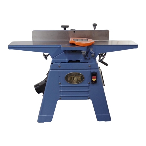
- Page 1 Model 0006 6” Jointer Owner’s Manual Oliver Machinery M-0006HS 08/2015 Copyright 2003-2015 Seattle, WA info@olivermachinery.net www.olivermachinery.net...
-
Page 2: Table Of Contents
Table of contents SAFETY INSTRUCTIONS ....................... 2 Receiving Jointer ........................4 Installation Stand Assembly ..................... 4 Safety Switch ........................... 7 Grounding Instructions ......................8 Adjustments ..........................9 Fence Adjustments: Tilt ......................10 Helical Cutterhead ........................12 Cutterhead Removal ......................12 Depth of Cut ........................... -
Page 3: Safety Instructions
SAFETY INSTRUCTIONS For Your Safety Read Instruction Manual Before Operating Jointer As with all machines, there is a certain amount of hazard involved with the use of this jointer. Use the machine with the respect and caution demanded where safety precautions are concerned. When normal safety precautions are overlooked or ignored, personal injury to the operator can result. - Page 4 Use recommended accessories. Consult the owner’s manual for recommended accessories. The use of improper accessories may cause risk of injury to persons. Never stand on tool. Serious injury could occur if the tool is tipped or if the cutting tool is unintentionally contacted.
-
Page 5: Receiving Jointer
Receiving Jointer Installation Stand Assembly Showing as below: Upon delivery, open shipping containers and check Prepare following parts for stand install that all parts are in good condition. Any damage should be reported to your distributor and A: Stand- Left ........ 1 shipping agent immediately. - Page 6 Installation Motor & Switch Installation Jointer Body & Stand Step 4: Put the motor & switch assembly on the Step 7: Put a large clean carton board or plastic paper Motor Bracket (D) and lock by Shoulder Screw on the floor to protect the jointer table top surface. (E)*4 &...
- Page 7 Checking Belt Tension Installation Pulley Cover Step 10: Pull down on the motor to achieve the The pulley cover is mounted with 2 Round Head desired belt tension (the correct belt tension is phillips screw w/teeth washer (L) to the threaded achieved when the belt can be deflected holes in the Stand.
-
Page 8: Safety Switch
Installation Blade Guard & Removal Installation Handwheel WARNING: Use the jointer guard for all Slip the handwheel (B) onto the elevation shaft (C) operations. Do not connect the plug to power (under the infeed table) then tighten with the Round Head phillips screw w/washers (D) source 1. -
Page 9: Grounding Instructions
outlet that looks like the one illustrated in Sketch D Grounding Instructions Fig. 1. The tool has a grounding plug that looks like the plug illustrated in Sketch D. WARNING: If the machine does not come Make sure the tool is connected to an outlet having the !... -
Page 10: Adjustments
Adjustments Warning: Always disconnect the machine from the power source before making any adjustments.. Failure to heed this warning can lead to serious personal injury. Note : Clockwise raises the table, counterclockwise lowers the table. To adjust outfeed table Fig. 3 The Jointer table is adjusted at manufactory and should no further adjustment required. -
Page 11: Fence Adjustments: Tilt
Table Gibs and Leveling The table gibs on your machine are factory adjusted and may never require readjustment. Should any adjustment become necessary, do the following: 1. Lightly loosen the 2 wing screw (A), Fig. 7. By loosening 6 lock nuts (B) then tighten 6 Set screws (C) , should be loose enough to move the table. - Page 12 Fence Stop Adjustments Periodically check the 90° and 45° backward (135°) tilt accuracy of the fence with an angle measuring device, such as an adjustable square or machinist’s protractor. 90º Fence Adjustment Referring to Fig. 9 : The 90º stop is controlled by the stop bolt (A) and the stop plate (B).
-
Page 13: Helical Cutterhead
Cutterhead Removal Helical Cutterhead If removal of the cutterhead is necessary, do the Knife inserts are dangerously sharp. WARNING: following: Use extreme caution when inspecting, removing or replacing knife inserts. WARNING: Disconnect jointer from ! power source. The knife inserts on the Jointer are four-sided. When dull, simply remove each insert, rotate it 1. -
Page 14: Depth Of Cut
Depth of Cut Depth of cut is determined by the height of the infeed table relative to the high point of the knives on the cutterhead. When facing the width of a board (as opposed to the edge of a board), NEVER attempt to take off more than 1/64"... -
Page 15: Basic Operations
two handed push Basic Operations block Before making any cuts on the stock, make a few practice cuts by raising the infeed table to “ 0" and with the power disconnected. In this manner you will acquaint yourself with the feel of jointer operations. - Page 16 Surfacing: Long Boards left hand pushes down toward fence The use of push blocks will help to insure as right hand against hands coming in contact with cutterhead starts feed in the event of a kickback and as trailing end of board passes over cutterhead.
- Page 17 Jointing (or Edging) Never edge a board that is less than 3 inches move fence forward wide, less than 1/4 inch thick, or 12 inches to expose only amount of cutterhead required long, without using a push block. CAUTION: When workpiece is twice the è...
-
Page 18: Push Blocks
Skewing ( Shear Cutting) When edging or facing burl or birds-eye maple, it is not unusual to deface or mar the surface being finished. This is caused by the cutterhead blades a t times cutting against the grain. In order to prevent the defacing or marring of this type wood, it is necessary to skew, or angle finish, the material being worked. -
Page 19: Wiring Diagrams
Wiring Diagrams... -
Page 20: Parts Diagrams
Parts Diagrams... -
Page 23: Parts List
Parts List Part No. Descriptions Q'ty 230031-619 KNOB FENCE 006003-091 FLAT WASHER 13*28*3.0t 380209-901 T-NUT 051301-000 FENCE BRACKET 230032-000 LOCKING HANDLE 006003-097 FLAT WASHER 13.5*40*3.0t 170047-901 PLATE STOP 290003-901 BOLT SHOULDER 011002-103 SPRING PIN 4*12 130055-903 SLEEVE FENCE 130009-903 BLOCK ASM DEPTH 360068-901 SHAFT LOCK 003003-708... - Page 24 Part No. Descriptions Q'ty 003305-706 PAN HD SCREW 5/32"-32NC*5/8" 920170-001 HANDWHEEL 240001-000 KNOB OUTFEED 57-2 924263-001 HELICAL CUTTERHEAD ASSEMBLY BYRD 3 SLOTS 030206-002 BALL BEARING 6202 050018-901 BEARING HOUSING 012003-009 5*5*25 030207-002 BALL BEARING 6203 050019-901 BEARING HOUSING 003201-702 SET SCREW 1/4"-20NC*3/8"...
Need help?
Do you have a question about the 0006 and is the answer not in the manual?
Questions and answers