
Related Manuals for Oliver M-1013


Summary of Contents for Oliver M-1013
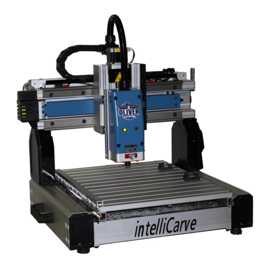
- Page 1 1013 intelliCarve Owner’s Manual Oliver Machinery M-1013 7/2011 Copyright 2003 Seattle, WA info@olivermachinery.net www.olivermachinery.net...
-
Page 2: Warranty
Warranty Oliver makes every effort possible to assure that its equipment meets the highest possible standards of quality and durability. All products sold by Oliver are warranted to the original customer to be free from defects for a period of 2 (two) years on all parts, excluding electronics and motors, which are warranted for 1 year. -
Page 3: Safety And Warnings
4. Before turning the power on, make sure the surroundings are clear of obstacles. 5. When you turn the power on, the axis return to the Home Point coordinates automatically. 6. Avoid the risk of danger; not play or run in the work area. -
Page 4: Table Of Contents
Unpacking Your intelliCarve ........................9 Standard Packaging ........................9 Getting to Know Your intelliCarve....................... 10-11 The Components ........................10 X/Y/Z Axis System ........................11 Install The Cutting Tool ..........................12 Cutting Tools ............................13-14 Conical Bit ..........................13 End Mill Bit ..........................14 Installing i-Picture Software ........................ -
Page 5: Overview
2D or 3D carvings, signs, or decorative mouldings request a ‘post processor file’ from your CAD/CAM software provider to run the intelliCarve machine. Note: Oliver does not guarantee the outcome of the work piece due to the table movement of the Y-axis. - Page 6 Technical Features Easy picture engraving by i-Picture’s intuitive picture to g-code convertor File transferred to intelliCarve via USB flash drive Pause function during carving Repeatable origin Adjustable jog speed in manual mode Adjustable carving speed Metric/Imperial system available Supports manual carving without program Maximum engraving area simulation Supports file category tree structure Spindle and stepper motors overload protection...
-
Page 7: Specifications
Specifications 1013 intelliCarve Item Description Spec Travel X axis 331mm(13") Y axis 457mm(18") Z axis 76mm(3") Tool ¼” shank OD conical R1/32” (0.8mm) / end mill D1/8” (3.2mm) cutter Cut depth Max 25.4mm(1") Spindle speed 15000rpm motor 150w DC brushless... - Page 8 Specifications (cont.) Dimension & Weight 10.2 Space (WxL) 630x560x530mm(25.8x22.0x20.8”) 10.3 weight 28 Kg 61.6lbs Others 11.1 power in AC 110V 6A 50~60Hz 11.3 software i-Picture for intelliCarve...
-
Page 9: Unpacking Your Intellicarve
Unpacking Your intelliCarve Please unpack your intelliCarve with care. If you discover the machine has been damaged, please report the damage to the freight carrier. Standard Packaging 1. Tool Box 2. USB flash drive 6. End mill bit, 3.2mm Diameter - I-picture software 7. -
Page 10: Getting To Know Your Intellicarve
Getting to Know Your intelliCarve Fig. 2 Fig. 3 The Components (see Fig. 2-3) 1. Spindle motor 7. Emergency stop 2. Spindle lock 8. Power switch 3. Table 9. USB port 4. Work piece hold downs 10. Lift handle (left) 5. -
Page 11: X/Y/Z Axis System
The Axis System The axis movements are defined according to the operator’s position (facing the front spindle). Directional Conventions 1. + X: spindle head moves right 2. - X: spindle head moves left. 3. +Z: spindle head moves up. 4. - Z: spindle head moves down. -
Page 12: Install The Cutting Tool
Installing the Cutting Tool Press pin slightly. Rotate spindle while pressing the pin in order to engage the lock. Loosen the nut with an open end wrench turning clockwise. Release the bit. To install a new bit, place the collet into the nut. Then put the bit into the nut and collet. -
Page 13: Cutting Tools
Cutting Tools Conical Bit Tool Model No. 381044-000 Material: Carbide Flute: 2 Flute length: 1” / Cut depth: Max 1” Shank diameter: ¼” Overall length: 2.36” Cutting edge radius: 0.8mm Various types of woods. ... -
Page 14: End Mill Bit
Cutting Tools (cont.) End Mill Bit Tool model No. 381020-000 Material: Carbide Flute: 2 Flute length: 0.47”/ Cut depth: Max 0.45” Shank diameter: ¼” End mill diameter: 3.175mm Overall length: 2.36” Various types of woods. ... -
Page 15: Installing I-Picture Software
Installing i-Picture Software When you purchase the intelliCarve, it comes with i-Picture software. i-Picture converts your image files (gif, png, bmp & jpg) to a .gee file in order for intelliCarve to perform. To begin using i-Picture software it first must be loaded into your personal computer. - Page 16 Endmill_D_1/8”: end mill [English]. Flat diameter: 1/8”.Type-B2 Tool Model No: 381020-000. Feed Depth per Cycle is the depth of cut (Z axis) per cycle. The default is set to be 24mm, but it is adjustable. For example: when Z is 10mm and Feed Depth per Cycle is 24mm, the cutter will carve the workpiece in a single pass.
- Page 17 Settings (cont.) XY Origin Position represents your picture and how it will be oriented on your work piece. (However this will ultimately be determined when you set the spindle to your preferred starting point on the work piece, but this will be discussed later in section 7.) If using a single piece of material for one carving it may be advantageous to start in the center as this is an easy point to find on your material.
- Page 18 Using i-Picture (cont.) 3. Converting a file Once your settings have been entered it is time to convert the image to a .gee code file. Click Convert to save the file in [.gee] format. A screen will pop up saying ‘It will take a few minutes, please Wait’...
-
Page 19: Getting Ready To Carve
Getting Ready to Carve Powering Up the intelliCarve **Ensure carving bit is secure in machine before proceeding** 1. Insert the flash drive into the USB slot. (see picture ‘A’) 2. Rotate emergency stop button clockwise to release. (see picture ‘B’) 3. -
Page 20: Setting The Work Piece On The Table
Setting the work piece on the table The left fence with the ruler represents the Y-axis. Make sure that the Y dimension of your carving is within the minimum and maximum dimension on the ruler. It is important for the work piece to be held securely in position on the work table. -
Page 21: Using The Control Panel
Setting Up To Carve (cont.) Using the control panel . When you first turn the machine on you will notice . The next screen to appear is the main operating the control panel display will read: screen as seen below. Use the arrow button on the controller to set the cursor to ‘Select file’... - Page 22 Use the X,Y and Z plus and minus keys to move the spindle to the center of your work piece. Note that for the Z axis, move the spindle so that the tip of the cutting tool just touches the work piece surface.
- Page 23 Using the control panel (cont.) . The screen will now show the X,Y,Z origin points confirmation set to zero: . Press the ‘BACK’ key on the keypad and the following screen will appear: If you wish to see the spindle travel around the outside border of your carving, move the cursor to ‘Border’ and press.
-
Page 24: Tips
Tips 1. When working with thin materials or cutting through your work piece it becomes necessary to place your project on a sacrificial board to prevent damage to the machine. Double sided tape such as white carpet tape is helpful to secure the pieces together. 2. -
Page 25: Advanced Operations
ArtCam. Check with your supplier for the post processor file required for your software to run the intelliCarve. There may be some limits to the projects you can produce due to nature of the Y-axis travel. Possibly, intricate work where fitting with another part is required may be a problem. Oliver Machinery is not responsible for work done using after market CAD/CAM software. -
Page 26: Positioning By Coordinate
User can move spindle to certain position by coordinate input: Step 1. Select ”Position” and press Step 5. Press up or down key to input coordinate reading, for this example, X axis reading is 103.6. Step 2. Select “coordinate mode” and press Step 6. -
Page 27: Turn Spindle On/Off In Manual Jog Mode
Advanced Operations (cont.) Turn on/off spindle in manual jog mode The default setting is ‘Spindle Motor Off’ Example:Turn Spindle Motor On Step 1. Select “Position “and press Step 2. Select “Spindle Motor Off” then press Cursor turns to block flash for adjustment status Step 3. -
Page 28: Changing Units From Metric To Imperial
Advanced Operations (cont.) Imperial / Metric Unit Change The iCarver default unit is Metric scale in mm, unit can be switched to Imperial in inches. Example: Change Unit from Metric (mm) to Imperial (inches) Step 5. Press “Down” key on keypad to change to Step 1. -
Page 29: Troubleshooting
& Hex wrench; and/or Use the tools that come in their travel areas. rotate the screw on Z with the unit to adjust the axis. lead screws. The unit will set the 3 ax- Contact your local dealer g. Restart the Start... - Page 30 Contact your local dealer Clean the lead screw & The axes move awk- or distributor if this does rail in which the axis wardly. not help. Select “Position” on the moves awkwardly. Control Panel, but the axes move improperly.
- Page 31 Troubleshooting During operation: Item Problem Check up Solution Note Ensure axes make a small shift. Time counts down shows on the display. Turn off Emergency Button to stop carving the project. Turn off the power switch in the rear of Select “Enter”...
- Page 32 Troubleshooting During operation: Item Problem Check up Solution Note Turn on Emergency Stop button. Turn off the power switch. Unsecure the nut on Use wrenches to re-install the bit the bit. Unload the ER-11 Bit breaks while carving. chuck The causes of Bit breaks: To lock the bit, push up 1.
-
Page 33: Parts List
1 HQ021100 128 040401-000 Screwdriver 1號*75 129 660175-000 Tool Box Plastic(Clear)175(L)*110(W)*95(H) 029402-101 M6*1.0P*16/6.1*12.3/6.3*13*1.0t Hex. Screw w/Spring and Flat Washer 310247-909 Z Axis Rail (Left) 6061 1 FH010063 310253-909 Z Axis Rail (Right) 6061 1 FH010069 310270-909 Z Axis Nut Bracket 6463... - Page 34 27 490778-000 LED Light (Red) 28 945445-000 Name Plate Assembly Oliver-110V 29 000101-103 CAP Screw M4*0.7P*12 30 499015-000 Step Motor 31 310265-909 X Axis Motor Bracket 6463 2 FH010097 32 002602-102 CAP Lock Screw M6*1.0P*20 4 HA310410 33 173170-904 Z Axis Guard Plate...
- Page 35 59 173120-904 X Axis Link Bracket SPHC 1 FH010113 60 021704-000 Sleeve AMB-3 65mm 61 310272-909 Cooler Panel 6463 1 FH010105 62 330051-000 Hex. Bolt M3*0.5P-10L 8 FJ010607 63 310331-909 Control Panel Cooler Plate 64 000301-206 Round Head Screw M3*0.5P*10 65 950536-000 Control Panel Assembly .1 490760-000 Control Panel...
- Page 36 .5 000304-107 Round Head Screw M6*1.0P*16 1 HA040708 103 130277-000 Gear 1 FH010095 104 001904-104 SET Lock Screw M4*0.7P*8 105 310258-909 Y Axis Motor Bracket 6463 1 FH010088 106 173236-000 Plate 107 000104-708 CAP Screw M8*1.25P*25 108 250123-615 Handle 2 PG920008...
Need help?
Do you have a question about the M-1013 and is the answer not in the manual?
Questions and answers