
Related Manuals for Oliver 4235


Summary of Contents for Oliver 4235
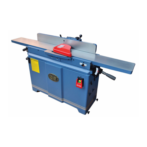
- Page 1 4235 8” Parallelogram Jointer Owner’s Manual Oliver Machinery M-4235 8/2019 Seattle, WA Copyright 2003-2019 info@olivermachinery.net www.olivermachinery.net...
- Page 2 CAUTION: Before using this 8” Parallelogram Jointer, read this owner’s manual completely and follow all its safety and operating instructions. QUESTIONS? If you have any questions or issues with this jointer, please call our Customer Service Center at 1-800-559-5065 or visit our website at www.olivermachinery.net.
-
Page 3: Table Of Contents
TABLE OF CONTENTS Warranty Information…....4 Operation…………………………. Warning……………………………… A. Switch Assembly……………… 30 Electrical Requirement & Safety… 6 B. Know Your Workpiece………... 30 Important Safety Instructions……. 7 C. Fence…………………………… 31 Product Specifications……………. 12 D. Set Depth of Cut………………. 31 Product Overview………………….. 13 E. -
Page 4: Warranty Information
WARRANTY INFORMATION Oliver Machinery makes every effort to assure that its equipment meets the highest possible standards of quality and durability. All products sold by Oliver Machinery are warranted to the original customer to be free from defects for a period of two (2) years on all parts excluding electronics and motors which are warranted for one (1) year from the date of shipment. -
Page 5: Warning
⚠WARNING Read and understand this manual completely and observe all warning labels on the machine. Oliver Machinery has made every attempt to provide a safe, reliable, easy-to-use piece of machinery. Safety, however, is ultimately the responsibility of the individual machine operator. -
Page 6: Electrical Requirement & Safety
Cord Length (feet) Amperage 25’ 26’ – 50’ 51 – 100’ 101 – 150’ Machine Tag American Wire Gauge Number 0 – 6 6 – 10 10 – 12 12 – 16 Not Recommended Oliver 4235 Owner's Manual... -
Page 7: Important Safety Instructions
“horseplay” are careless acts that can result in serious injury. • DRUGS, ALCOHOL AND MEDICATION. Do not operate this machine while under the influence of drugs, alcohol, or any medication. Oliver 4235 Owner's Manual... - Page 8 • THIS MACHINE IS DESIGNED FOR SURFACING WOOD PRODUCTS ONLY. Do not use this Oliver jointer for other than its intended use. Do not use this machine to cut any kind of metal or substance other than wood. If used for other purposes, Oliver disclaims any real or implied warranty, and guarantee is null and void.
- Page 9 RED TAGGED to show it should not be used until the maintenance is complete. • REPLACEMENT PARTS. Use only genuine Oliver Machinery factory authorized replacement parts and accessories; otherwise, the warranty and guarantee are null and void.
- Page 10 • Avoid awkward operations and hand positions where a sudden slip could cause a hand to move into the blade. • Hold workpiece firmly. • Never reach your hands underneath the workpiece while the cutterhead is rotating. Oliver 4235 Owner's Manual...
- Page 11 When Done Using the Jointer • Turn off and unplug the jointer when done. • Lock the jointer to prevent unauthorized use. • Clean and store the jointer in a safe, dry place after use. Oliver 4235 Owner's Manual...
-
Page 12: Product Specifications
PRODUCT SPECIFICATIONS MODEL 4235.201 8” X 72” PARALLELOGRAM JOINTER WITH HELICAL CUTTERHEAD AND BUILT-IN MOBILE BASE Motor……………………………….……………...………………. 2HP 1PH 220V 8 Amps Infeed Table Travel…………………………….………..……………………………….1/2” Cutterhead Speed……………………………….……..…...……5,500RPM V-Belt Driven Number of Knives………………………………………………………………….36 Inserts Rabbeting Capacity……………………………….…………...………………………...1/2” Max. Cutting Width……………………………………………………………………….…8” Max. Cutting Depth……………………………………………………………………….1/8”... -
Page 13: Product Overview
Lock Knobs Fence Tilt Handle 90° Stop 45° Stop Bolt Block Fence Movement Knob 135° Stop Bolt Fence Lock Lever 90° Stop CAP Screw Back Lifting Hook Location Fence Tilt Lock Rear Access Panel Dust Port Oliver 4235 Owner's Manual... -
Page 14: Uncrate Your Jointer
• Insert Box x 1 • 8x10 Double Wrench 8. Owner’s Manual • 11x13 Double Wrench 5. Hook Assembly • Spring Washer x 4 • Cap Screw x 4 • Hook x 2 FIG. 2 Owner’s Manual Oliver 4235 Owner's Manual... -
Page 15: Preparation For Set Up
6. If powered lifting is desired, Install FIG. 4 the lifting hooks on the machine, one in the front side and one in the back Mobile Base as shown in FIG. 3 using the Lock Knobs included 6mm hex. wrench. Oliver 4235 Owner's Manual... -
Page 16: Assembly & Installation
STEP 2: Secure the hose with a hose away from the fence and release it to clamp (not included). Make sure the make sure it is installed properly. hose is attached to the dust port tightly. Oliver 4235 Owner's Manual... -
Page 17: Adjustments
FIG. 7 on the rear access panel and REMOVE THE CARRIAGE SCREWS remove the panel as shown in FIG. 8. AND NUTS. FIG. 9 Pulley Approximately ¼” Deflection FIG. 7 Motor Mounting FIG. 10 Carriage Bolts & Nuts FIG. 8 Oliver 4235 Owner's Manual... -
Page 18: Belt Replacement
The fence can slide forward or backward across the width of the tables Buffer as well as being tilted forward or backward to any angle down to 45°. To do so, follow the steps below. Slide Fence Oliver 4235 Owner's Manual... - Page 19 STEP 4: Use fence tilt handle to tilt the NOTE: If the 90° fence stop doesn’t fence backward and slide it back until it seem to be accurate, follow STEP 6 to stops at the 135° fence stop bolt. STEP 11. Oliver 4235 Owner's Manual...
-
Page 20: Fence Stops
STEP 4: Use fence tilt handle as in FIG. 13 to tilt the fence forward and slide it until it stops at the 45° fence stop bolt. STEP 5: Lock fence tilt lock and begin to jointing at 45° bevel. Oliver 4235 Owner's Manual... -
Page 21: Fence Removal
Hex. Nut x 2 Outfeed Table STEP 1: While the machine is still disconnected from power source, cutterhead guard is removed, and fence is away or removed, remove rear access panel to obtain access of the cutterhead body. Oliver 4235 Owner's Manual... - Page 22 FIG. 19. NOTE: When the half-moon shape packing on the CAP screw touches the plate, it results in the lowest point of the Oliver 4235 Owner's Manual...
- Page 23 CAP Screw guard and rear access panel. If it does Plug not fit evenly flat against both infeed able outfeed tables in any position, go to Table Parallelism Adjustment. Oliver 4235 Owner's Manual...
-
Page 24: Outfeed Table Height Adjustment
STEP 5: Lock outfeed table at that as STEP 4 for outfeed table. height. STEP 7: Verify parallelism in each position as in FIG. 29, tighten set screws in eccentric bushings on infeed table. Oliver 4235 Owner's Manual... -
Page 25: Depth Of Cut
STEP 6: Move position plate as C in FIG. 31 to contact position bracket as D Infeed Table Depth in FIG. 31. Stop Release Knob STEP 7: Tighten A screw in FIG. 31. ○ Infeed Table Adjustment Lever Oliver 4235 Owner's Manual... -
Page 26: Rotating Or Replacing Inserts
The spring quality of cuts. won’t lose its tension and cutterhead STEP 4: Remove torx screws with the guard will always bounce back. included torx screwdriver as in FIG. 33. FIG. 33 Individual Insert Shown Oliver 4235 Owner's Manual... -
Page 27: Cutterhead Removal
35 from the rabbeting table. from cutterhead pulley. FIG. 35 FIG. 38 CAP Screw STEP 5: Remove screws and washers from infeed table as in FIG. 36 to remove rabbeting table. Belt Guard Driving Belt FIG. 36 FIG. 39 Oliver 4235 Owner's Manual... - Page 28 STEP 10: Place the table base assembly on top of two tables to have an access to the bottom of the cutterhead. Remove the lock washer and cap screw from the bearing block housing as in FIG. 41. Oliver 4235 Owner's Manual...
-
Page 29: Pulley Alignment
STEP 10: Re-install fence, belt cover straight edge against pulley faces as in and rear access panel. FIG. 43. Cutterhead Cutterhead Set Screw Pulley £ Alignment Motor Pulley Motor Set Screw FIG. 42 View from Top FIG. 43 Oliver 4235 Owner's Manual... -
Page 30: Operation
• Remove foreign objects such as nails, staples or any other foreign objects that could damage the cutterhead. • Do not joint workpiece that is smaller than ½” thick and 2” wide. Oliver 4235 Owner's Manual... -
Page 31: Fence
STEP 5: Place the workpiece against the same fashion as the left hand in fence and infeed table firmly. FIG. 47. More steps on next page FIG. 47 Oliver 4235 Owner's Manual... -
Page 32: Edge Jointer
Do not set cuts deeper than 1/8” tables. in a single pass. STEP 5: Several passes may be STEP 3: Hold the best face of the necessary for the desired result. workpiece firmly against the fence throughout the feeding. Oliver 4235 Owner's Manual... -
Page 33: Rabbeting
STEP 4: Have the push blocks ready. STEP 5: Place workpiece firmly against the fence and infeed table. STEP 6: Feed the workpiece through completely across cutterhead while keeping it firmly against fence and tables during the entire cut. Oliver 4235 Owner's Manual... -
Page 34: Maintenance
I. ROTATE OR REPLACING INSERTS on page 26. Before rotate and replace inserts, the inserts, screws and the cutterhead platform must be free of dust to make sure the inserts are placed properly. Oliver 4235 Owner's Manual... -
Page 35: Troubleshooting
2. Workpiece not held with even the front end pressure when feeding through pressure when feeding through Finished stock is Tables are not level with each other Level one of the tables to the other concave or convex in the middle Oliver 4235 Owner's Manual... -
Page 36: Parts & Diagram
Maintenance Records:... - Page 37 Oliver 4235 Owner's Manual...
- Page 38 Oliver 4235 Owner's Manual...
- Page 39 Oliver 4235 Owner's Manual...
- Page 40 Oliver 4235 Owner's Manual...
- Page 41 Parts List for 4235 Item Part No. Description Specification 240080-904 Knob 001902-109 Set Lock Screw M6*1.0P*6 010003-000 S Ring STW-12 381336-901 Gear Shaft 006001-087 Flat Washer 250372-615 Knob 360038-901 Shaft for Knob 003103-102 Cap Screw 1/4"-20NC*1/2" 172285-905 Flat Washer 13*35*5.0t 009011-100 Hex.
- Page 42 Parts List for 4235 Item Part No. Description Specification 011002-105 Spring Pin 4*20 380082-902 000701-103 Flat Head Hex. Screw M5*0.8P*12 171841-902 Fence Guide 006001-034 Flat Washer 6.7*16*2.0t 051355-000 Fence Slide Bracket 006722-100 Wavy Washer WW-19 (19.05*26) 012003-008 5*5*22 381409-902 Cutterhead Pulley...
- Page 43 Parts List for 4235 Item Part No. Description Specification 174604-000 Plate 002603-101 Cap Lock Screw M5*0.8P*10 361326-902 Shaft for Knob 174784-904 Positioning Plate 000103-108 Cap Screw M6*1.0P*25 006303-100 Spring Washer 6.5*10.5 130393-903 Wedged Block 361370-902 Shaft 002602-101 Cap Lock Screw M6*1.0P*12...
- Page 44 Parts List for 4235 Item Part No. Description Specification 006703-100 Wavy Washer WW-10 000105-101 Cap Screw M10*1.5P*20 000304-203 Pan Head Philips Screw M6*1.0P*12 006002-032 Flat Washer 6.6*13*1.0t 250052-615 Dust Port 174596-000 Cabinet 250399-615 Wheel 008306-100 Lock Nut M8*1.25P 000003-313 Hex. Screw M8*1.25P*60...
- Page 45 Parts List for 4235 Item Part No. Description Specification 158.7 570695-000 Ground Sticker 158.8 008002-200 Hex. Nut M4*0.7P(7B*3.2H) 158.9 006501-100 Toothed Washer 4.3*8.5(BW-4) 158.10 000302-101 Pan Head Philips Screw M4*0.7P*6 174239-904 Backing Plate 020003-000 Pan Head Philips Screw M4*0.7P*6 453012-013...
-
Page 46: Wiring Diagram
WIRING DIAGRAM Oliver 4235 Owner's Manual...
Need help?
Do you have a question about the 4235 and is the answer not in the manual?
Questions and answers