
Related Manuals for Oliver 4710


Summary of Contents for Oliver 4710
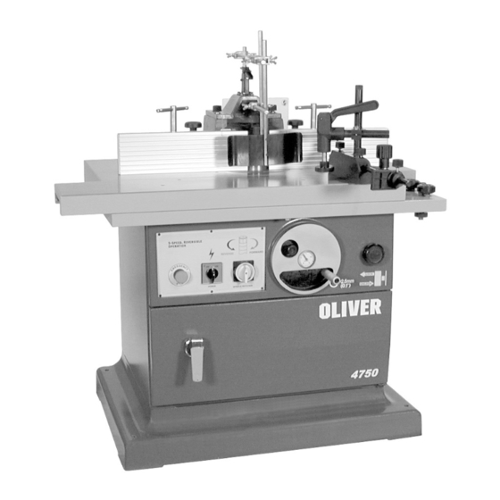
- Page 1 4710 and 4750 Shapers Owners Manual (4750 - Sliding Table Shaper Shown) Oliver Machinery M-4710 8/2003 © Copyright 2003 Seattle, WA info@olivermachinery.net www.olivermachinery.net...
-
Page 2: Warranty
Oliver makes every effort possible to assure that its equipment meets the highest possible standards of quality and durability. All products sold by Oliver are warranted to the original customer to be free from defects for a period of 2 (two) years on all parts, excluding electronics and motors, which are warranted for 1 year. -
Page 3: Warnings
WARNING Read this manual completely and observe all warning labels on the machine. Oliver Machinery has made every attempt to provide a safe, reliable, easy-to-use piece of machinery. Safety, however, is ultimately the responsibility of the individual machine operator. As with any piece of machinery, the operator must exercise caution, patience, and common sense to safely run the machine. - Page 4 Misuse: Do not use this Oliver shaper for other than its intended use. If used for other purposes, Oliver disclaims any real or implied warranty and holds itself harmless for any injury or damage which may result from that use.
-
Page 5: Table Of Contents
Sliding Table Adjustment...........................16 Troubleshooting............................16-17 Specifications Model (Stationary Table)........................4710 Stock No. 4710.001....................5 HP, 1 Ph, 220V Only Stock No. 4710.002................5 HP, 3 Ph, 220/440V Prewired 220V Table Dimensions........................41 1/2" x 29 1/2" Table Height............................34-1/4"H Spindle Speed (RPM)................3,000, 4,000, 6,000, 8,000, 10,000 Spindle Direction...........................Reversible Maximum Tool Diameter Below Table......................7"... -
Page 6: Contents Of The Shipping Container
Contents of the Shipping Container Oliver Shaper 1. Shaper (sliding table or stationary table) 1. Fence Assembly 1. Fence Assembly Cover 1. Miter Gauge Assembly Toolbox Contents 4. Spindle (1-1/4”) 1. Grease Gun 6. Open End Wrenches 10. Hex Angle Wrenches 1. -
Page 7: Lifting The Shaper
Lifting the Shaper A forklift can be used to lift the machine from underneath, or with a sling underneath the table. The shaper must be positioned on a smooth, level surface leaving enough room maintenance feeding stock into machine. ! WARNING Disconnect machine from the power source before any maintenance, service or assembly is performed. -
Page 8: Miter Gauge
4. Fasten bar (A, Figure 4) to the front of the fence support (B, Figure 4) using one locking handle and washer (C, Figure 4). 5. Slide aluminum fence (D, Figure 4) onto the bar. 6. Repeat for opposite side. Mitre Gauge 1. -
Page 9: Installing Spindles
Installing Spindles ! WARNING Disconnect machine from the power source before any maintenance, service or assembly is performed. Failure to comply may cause serious injury! 1. Remove the three socket head cap screws holding the smaller table insert in place. Raise the spindle shaft by turning the handwheel (A, Figure 7) until the insert can be removed. -
Page 10: Electrical Connections 3 Phase And 1 Phase
Electrical Connections for a 1-Phase Unit bevel washer (A, Figure 10) on the bottom of the draw bar as shown in Figure 10. This shaper is 1-Phase, 220V only. Oliver Machinery recommends using a dedicated 9. Assemble and securely tighten the hex nut circuit. -
Page 11: Controls
Controls Emergency Stop: Stops all electrical functions of machine, but the saw still has power. To reset rotate switch clockwise until the button pops out. Power Switch: Stops and starts the spindle. Will not work when “Emergency Stop” is engaged, or if the spindle rotation switch is in the “Off”... -
Page 12: Speed Change And Belt Adjustment
Speed Change and Belt Adjustment sufficient capacity and suction for your shaper. Always use dust collection Your machine is supplied with a 5-step pulley system that provide spindle speeds of 3000, 4000, 6000, 8000 and 10000 RPM. A speed chart, shown in Figure 14, is located on the inside of the front cabinet door for easy reference of the belt position on the pulleys for the five speeds available. -
Page 13: Straight Work
Straight Work ! WARNING Keep guards in place and in working order. Always use fence assembly when the work permits. Failure to comply may cause serious injury! Using the fence is the safest and most satisfactory method of shaping, and it should always be used when the work permits. -
Page 14: Position Of Collars
Position of Collars When shaping with collars, the collar must have sufficient bearing surface, as shown in Figure 20. Also the work must be fairly heavy relative to the cut being made. Under no circumstances should a short, light workpiece be shaped against the collars, as shown in Figure 21. -
Page 15: Copying (Shaping With A Jig)
Copying (Shaping with a Jig) When using the same procedure on multiple workpieces, a jig or template can be made to facilitate the operation: 1. Prepare Figure accommodate your original workpiece. 2. Place the jig against the table ring guide shoulder (B, Figure 24). -
Page 16: Sliding Table Adjustment
Sliding Table Adjustment Whenever the table is not traveling properly loosen the socket head cap screw (A, Figure 27) and turn the eccentric (B, Figure 27) with a wrench. Adjust until the table is traveling properly and tighten the socket head cap screws while holding eccentric. - Page 17 1. Sharpen by honing on flat side 1. Dull cutter 2. On hardwoods take light cuts; Stock burns 2. Cutter too deep attain full depth of cut with several passes 3. Forcing work 3. Feed slowly and steadily 1. Replace cutter 1.
Need help?
Do you have a question about the 4710 and is the answer not in the manual?
Questions and answers