
Related Manuals for Oliver 4240


Summary of Contents for Oliver 4240
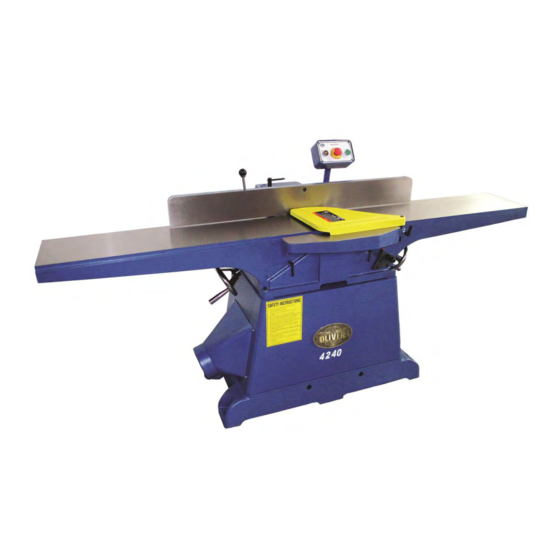
- Page 1 4240 10” Jointer Owner’s Manual Oliver Machinery M-4240 01/2015 Seattle, WA Copyright 2003-2015 info@olivermachinery.net www.olivermachinery.net...
- Page 2 Oliver makes every effort possible to assure that its equipment meets the highest possible standards of quality and durability. All products sold by Oliver are warranted to the original customer to be free from defects for a period of 2 (two) years on all parts, excluding electronics and motors, which are warranted for 1 year.
- Page 3 WARNING Read this manual completely and observe all warning labels on the machine. Oliver Machinery has made every attempt to provide a safe, reliable, easy-to-use piece of machinery. Safety, however, is ultimately the responsibility of the individual machine operator. As with any piece of machinery, the operator must exercise caution, patience, and common sense to safely run the machine.
- Page 4 16. Misuse: Do not use this Oliver jointer for other than its intended use. If used for other purposes, Oliver disclaims any real or implied warranty and holds itself harmless for any injury or damage which may result from that use.
-
Page 5: Table Of Contents
Stock No.(5HP, 3PH, 220/440 Volt, pre-wired 220 Volt) ..............4240.004 Stock No.(3HP, 1PH, 220 volt, spiral head) ..................4240.101 Stock No (5HP, 3PH, 220/440 volt, pre-wired 220 Volt, spiral head) ..........4240.104 Infeed Table Travel (in.) ..........................5/8 Cutterhead speed (RPM) ........................5000 Number of Knives (Straight) .......................... -
Page 6: Warnings
Oliver 4240 – 10” Jointer Uncrating the Machine The machine should arrive as show in Figure 1. Uncrate the machine and inspect the unit for signs of shipping damage. If damage is found, contact your dealer immediately. Unbolt the machine from the pallet. Retain all packaging materials in case it becomes necessary to ship the machine to another site. -
Page 7: Dust Collection
Dust Collection The 6” dust collection port (A, Figure 4) is located below the outfeed table. Typically flex hose is used to run from this point to a central trunk line. Note: Do not operate the jointer without dust collection. Electrical Connections WARNING! Electrical connections and wiring must be... -
Page 8: Fence
Fence Once any adjustments are made be sure to WARNING! lock them into place before jointing. Never make any adjustments with the machine running! Installation of the Fence The fence, although completely assembled, requires bolting to the machine. 1. Set the fence bracket (Figure 8) on top of the fence support bracket (Figure 7) lining up the key slides ‘A’... -
Page 9: Knives
Knives WARNING! The knives are extremely sharp. caution when handling. Knife Removal 1. To expose the cutterhead, move the fence all the way back. 2. Back down both the infeed and outfeed tables to their lowest position. Be sure to loosen the lock on bot the infeed and outfeed tables before doing so. -
Page 10: Knife Setting
Knife Setting (cont.) Adjusting the Outfeed Table 1. Once the knives are set it is now time to set the outfeed table. For proper operation the height of the outfeed table must be set to the highest point of the cutting circle. To do this, set a straight edge on the outfeed table as shown in Figure 13. -
Page 11: Spiral Head Option
Spiral Head Option 3. Starting in the middle of the knife, place the gib plate on the knife and lightly screw in one of the gib screws so that the knife tab If you purchased a machine with the spiral seats in the slot. -
Page 12: Operation
Operation WARNING! Keep all guards in place. Keep hands away from the cutterhead! Always use push stick when possible. Failure to comply may cause serious injury. Hand Safety and Placement Never pass the hands directly over the cutter knife. As one hand approaches the knives remove it from the stock in an arc motion and place it back on the stock in a position beyond the cutter knife. -
Page 13: Facing
Facing Once you have a good edge it is time to eliminate any warp or cup on the board. Keep in mind the outfeed table is the reference point and once the material is past the cutterhead, downward pressure should be applied to the outfeed table only. -
Page 14: Adjusting The Infeed Table Height
Adjusting the Infeed Table Height The height of the infeed table with respect to the cutting circle will determine the amount of material to be removed from the work piece. To raise or lower the table, turn the height adjusting wheel (A, Figure 27) below the infeed table to the desired height indicated by the guage (C, Figure 27). -
Page 15: Maintenance
Maintenance V-Belts After the first 20 hours of operation it is necessary to check the tension on of the V-belts. To do this, open the access panel (A, Figure 28) by removing the four corner screws. With medium finger pressure the belt should push in approximately ½”... -
Page 16: Troubleshooting
Troubleshooting Description of Symptoms Possible Cause Corrective Action 1. Fuse blown or circuit breaker 1. Replace fuse or reset circuit tripped breaker 2. Cord Damaged 2. Have cord replaced 3. Faulty switch 3. Replace switch Machine will not start 4. Not connected power 4. - Page 17 4240 Parts List Index Part No. Descriptions Spec. Q'ty JH010001 BASE JH010002 INFEED TABLE JH010003 OUTFEED TABLE JH010004 JH010005 SCREW JH010006 BLADE GUARD JH010009 SET BRACKET JH010017 BOLT JH010056 BALL JG010201 HANDWHEEL JG010504 BRACKET JG010505 BRACKET JG010507 BUSHING JG010509 SET SCREW 5/16-18NC*1-1/4"...
- Page 18 40S-3 JHOLO2O3 KNIFE LOCK BAR -L 40S-4 JH0L0204 KNIFE LOCK BAR -R 40S-5 JH0L0204 KNIFE LOCK BAR 40S-6 HA090404 ROUND HEAD SCREW M6*14 40S-7 PJ250008 KNIFE LOCK PIN 40S-8 JE0L0103 PACKING JH0L01 FLAT KNIFE CUTTERHEAD ASSY 40F-1 JH0L0101 CUTTERHEAD 40F-2 JH0L0102 KNIFE 40F-3 JH0L0103 KNIFE LOCKING BAR...
- Page 19 HX010500 HEX. NUT 1-4"-20NC HX010700 HEX. NUT 5/16"-18NC HX011400 HEX. NUT 1-2"-20NC JH010031 BASE JH010032 COVER JH010033 CHIP BRACK JH010034 DUST COLLECT JH0102 WIRE BOX JH010201 SWITCH BOX LOWER COVER JH010202 SWITCH BOX UPPER COVER JH010203 JH010204 HP170100 1/2" HS040402 PAN HEAD SCREW M4*0.7P*6 HS040403...
- Page 20 HA010508 HEX. SCREW M8*1.25P*16 HA020608 CAP SCREW M10*1.5P*16 HP020400 STAIN RELIEF ACC-2.5 HS010405 HEX. SCREW M6*1.0P*12 HS010759 HEX. SCREW M12*1.75P*100 HS040604 ROUND CROSS HEAD SCREW M5*0.8P*10 HS040610 ROUND CROSS HEAD SCREW M5*0.8P*20 HS100404 HEX. SCREW W/WASHER M6*1.0P*10 HW011200 HEX. NUT M12*1.75P HY019900 FLAT WASHER...
- Page 21 MH010053 T-WRENCH HR050400 180*250*0.15t PJ250008 121A JH0F0101 POWER CORD 3HP.1PH SJT 14AWG*3C 121B JH0F0201 POWER CORD 5HP.3PH ST 16AWG*4C JG1P01 KNIFE SETTING GAUGE ASSY FLAT KNIFE 123F JG1P0101 KNIFE GAGE JG1P0102 HF031800 E-RING JH1A0105 POINTER 126A HK013700 BELT M51 (3HP.1PH) 126B HK013500 BELT M49 (5HP.3PH)
Need help?
Do you have a question about the 4240 and is the answer not in the manual?
Questions and answers