
Related Manuals for Oliver 4260


Summary of Contents for Oliver 4260
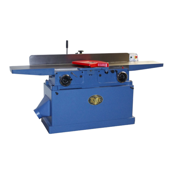
- Page 1 4260 12” Parallelogram Jointer Owner’s Manual Oliver Machinery M-4260 9/2019 Seattle, WA Copyright 2003-2019 info@olivermachinery.net www.olivermachinery.net...
- Page 2 In no event shall Oliver be liable for death, personal or property injury, or damages arising from the use of its products.
-
Page 3: Table Of Contents
Table of Contents SAFETY INSTRUCTIONS ........................2 Uncrating the Machine .......................... 5 Machine Preparation and Setup ......................5 Dust Collection ............................5 Electrical Connections .......................... 6 Grounding Instrctions ..........................6 On/Off Switch ............................7 Control Box ............................. 7 Cutterhead Guard Installing & Removal .................... 7 Cutterhead .............................. -
Page 4: Safety Instructions
SAFETY INSTRUCTIONS For Your Safety Read Instruction Manual Before Operating Jointer As with all machines, there is a certain amount of hazard involved with the use of this jointer. Use the machine with the respect and caution demanded where safety precautions are concerned. When normal safety precautions are overlooked or ignored, personal injury to the operator can result. - Page 5 Maintain tools with care. Keep tools sharp and clean for best and safest performance. Follow instructions for lubricating and changing accessories. Disconnect tools before servicing; when changing accessories, such as blades, bits, cutters, and the like. Reduce the risk of unintentional starting. Make sure switch is in off position before plugging in. Use recommended accessories.
- Page 6 Hand safety. It is good practice to move the hands in an alternate motion from back to front as the work continues through the cut. Never pass the hands directly over the cutter knife. As one hand approaches the knives remove it from the stock in an arc motion and place it back on the stock in a position beyond the cutterknife.
-
Page 7: Uncrating The Machine
Uncrating the Machine Uncrate the machine and inspect the unit for signs of shipping damage. If damage is found, contact your dealer immediately. Unbolt the machine from the pallet. Retain all packaging materials in case it becomes necessary to ship the machine to another site. Moving the Machine into Place Do not lift the jointer by the tables from the pallet to the shop position. -
Page 8: Electrical Connections
Never use an adapter between plug and outlet and always ground the machine. To convert from 220V three phase to 440V three phase new parts are required. Contact Oliver Machinery for details. With three phase power make sure the cutter head rotation is in the proper direction. -
Page 9: On/Off Switch
Control Switch The control switch comes mounted to the infeed table as shown Fig. 1 The control switch features an on and an off switch. The off switch features a lock that must be twisted clockwise to reset before the machine can be started. This machine features magnetic motor controls. -
Page 10: Cutterhead
Cutterhead Removal Helical Cutterhead If removal of the cutterhead is necessary, do the following: Knife inserts are dangerously sharp. Use extreme caution when inspecting, WARNING: Disconnect jointer from power removing, or replacing knife inserts. ! source. The knife inserts on the Jointer are four-sided. 1. -
Page 11: Fence
Fence The fence is assembled and comes mounted to the jointer. If it needs to be removed, take off by removing the bolts as shown Fig, 4 The width adjustment handwheel (D, Fig. 5) will need to be installed. WARNING: Never make any adjustments to the fence when the machine is running. -
Page 12: Hand Safety And Placement
Hand Safety and Placement Never pass the hands directly over the cutter knife. As one hand approaches the knives remove it from the stock in an arc motion and place it back on the stock in a position beyond the cutter knife. See Fig 7. When feeding the work piece, pressure is applied not only toward the cutterhead but against the fence and down to the table as well. -
Page 13: Edging
Edging To give a good straight edge for gluing or joining, set the fence square with the table. Remove the least amount of material required to obtain a straight edge. Hold the best face of the piece firmly against the fence throughout the feed. -
Page 14: Rabbeting
(B, Fig 13). Infeed Table Lock Fig. 13 The 4260 jointer is equipped with an infeed table lock that will limit the maximum depth of cut to 1/8” unless released by the operator. The lock must be released during any infeed table adjustment to prevent damage to the raising mechanism. -
Page 15: Lubrication
Lubrication Periodically apply a lightgrease to the tables up/ down lead screw. As well, apply a light oil to the dovetail ways from time to time to allow ease of movement. The cutterhead bearings are permanently greased for life and do not require care. Setting Table Coplanar To achieve optimal results from your jointer, the infeed and outfeed tables must be parallel front... -
Page 16: Coplaner Adjusting Continued
The machinist straight edge should lie evenly across the infeed and outfeed tables without a gap between the straight edge and tables. Move the straight edge across the tables and check for gaps at any position from front to back. If the steel straight edge does not lie evenly and gaps are found one or both tables may need to be adjusted to make the tables coplanar. -
Page 17: Basic Operations
Basic Operations Two handed push block Before m aking any c uts on t he s tock, m ake a f ew practice cuts by r aising t he i nfeed t able to “ 0" a nd with the power disconnected. In this manner you will acquaint yourself with the feel of jointer operations. - Page 18 Left hand pushes SURFACING: L ONG BOARDS down toward fence as right hand The use of p ush blocks w ill help to i nsure against starts feed hands coming in contact with cutterhead in the event of a kickback and as trailing end of board passes over cutterhead.
- Page 19 Move fence forward JOINTING (or EDGING) to expose only amount of cutterhead required Never edge a board that is less than 3 inches wide, less t han 1 /4 i nch thick, o r 12 i nches l ong, w ithout using a push block.
- Page 20 Push Blocks Push blocks are simple, yet necessary tools to assist the operator especially when jointing thin or short stock. Illustrated in Figure 30 are three types of push blocks commonly used in jointing. Push blocks may be obtained commercially or easily constructed.
-
Page 21: Troubleshooting
Troubleshooting Description of Symptoms Possible Cause Corrective Action 1. Fuse blown or circuit 1. Replace fuse or reset circuit breaker tripped breaker 2. Cord Damaged 2. Have cord replaced 3. Faulty switch 3. Replace switch Machine will not start 4. Not connected to power 4. -
Page 26: Parts List
Parts List for 4260 Item Part No. Description Specification 230262-000 Lock Handle 006002-096 Flat Washer 13.5*32*3.0t 000004-213 Hex Screw M10*1.5P*65 008007-200 Hex Nut M10*1.5P 000101-103 Cap Screw M4*0.7P*12 380832-901 923595-000 Handwheel Assembly 000203-103 Set Screw M6*1.0P*10 380827-901 Sleeve 050902-000 Bracket... - Page 27 Parts List for 4260 Item Part No. Description Specification 009004-100 Hex Nut 1/4"-20NC 230275-000 Set Screw 280165-000 Spring 230273-000 Screw Bolt 380825-901 Shaft Collar 923491-000 Up/Down Shaft Assembly 012003-004 5*5*15 360622-901 Shaft 012003-002 5*5*10 048201-201 Hex Lock Screw M8*1.25P*20 050731-902...
- Page 28 Parts List for 4260 Item Part No. Description Specification 011003-102 Spring Pin 5*16 021801-000 Lock Ring NB-1722 380469-902 Bolt 171756-000 Belt Guard 230324-000 Knob 000304-103 Pan Head Screw M6*1.0P*12 173232-156 Indicator 008007-100 Hex Screw M10*1.5P 000205-102 Set Screw M10*1.5P*30 160025-000...
- Page 29 Parts List for 4260 Item Part No. Description Specification 475002-006 CSA Cable SJT16AWG*5C*400mm 170977-901 Switch Board 150.08 Note: 440V 3Phase operation requires special components, contact Oliver Machinery. 490696-000 Connector 2000H-06 (Male) 475002-007 CSA Cable SJT16AWG*5C*1400mm 023311-000 Wire Clip ALC-110S 003303-102 Pan Head Screw 3/16"-24NC*1/4"...
Need help?
Do you have a question about the 4260 and is the answer not in the manual?
Questions and answers