
Related Manuals for Oliver 4230


Summary of Contents for Oliver 4230
- Page 1 4230 8” Jointer Owner’s Manual Oliver Machinery M-4230 10/2007 Seattle, WA © Copyright 2003 info@olivermachinery.net www.olivermachinery.net...
- Page 2 Oliver makes every effort possible to assure that its equipment meets the highest possible standards of quality and durability. All products sold by Oliver are warranted to the original customer to be free from defects for a period of 2 (two) years on all parts, excluding electronics and motors, which are warranted for 1 year.
- Page 3 WARNING Read this manual completely and observe all warning labels on the machine. Oliver Machinery has made every attempt to provide a safe, reliable, easy-to-use piece of machinery. Safety, however, is ultimately the responsibility of the individual machine operator. As with any piece of machinery, the operator must exercise caution, patience, and common sense to safely run the machine.
- Page 4 Misuse: Do not use this Oliver jointer for other than its intended use. If used for other purposes, Oliver disclaims any real or implied warranty and holds itself harmless for any injury or damage which may result from that use.
-
Page 5: Table Of Contents
Adjusting the Infeed Table Height......................13 Maintenance.............................13 V-Belts...............................13 Lubrication..............................13 Knives................................13 Table Leveling............................13 Troubleshooting............................14 Specifications Model No...............................4230 Motor..........................2HP, 1PH, 220 Volt Full load amps............................12 Infeed Table Travel (in.)..........................1/2 Cutterhead speed (RPM)........................5500 Number of Knives............................54 Rabbeting Capacity (in.)...........................1/2 Dust Port Diameter (in.)..........................4 Table Dimensions (L x W/in.)....................74-7/8 x 9-1/4 Table Height (In.)..........................30-1/2... -
Page 6: Warnings
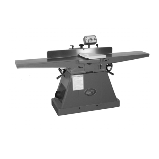
Oliver 4230 – 8” Jointer Uncrating the Machine The machine should arrive as show in Figure 1. Uncrate the machine and inspect the unit for signs of shipping damage. If damage is found, contact your dealer immediately. Unbolt the machine from the pallet. Retain all packaging materials in case it becomes necessary to ship the machine to another site. -
Page 7: Control Panel And Magnetic Starter
Machine Preparation and Setup (Cont.) V-Belts Control Panel and Magnetic Starter Remove the belt guard and set aside as shown Remove the control box and magnetic starter in Figure 6. Place the belts over the cutterhead from the jointer stand. Mount the control box to and motor pulley. -
Page 8: Dust Collection
Figure 4 Dust Collection The 4230 is supplied with a mountable 4” dust port. If using a dust collector mount the dust Figure 6 port as shown in Figure 5. Secure it in place, under the outfeed table, with the supplied machine screws. -
Page 9: Fence Operation
Fence Operation WARNING! Never make any adjustments with the machine running! Fence Legend The various adjustments, locks and handles are shown in Figure 8. 90 degree adjustment 90 degree flip stop. Angle lock handle. 45 degree adjustment. Width lock handle. Fence width lock. -
Page 10: Knives
2. Carefully adjust the table height by turning the handwheel (A, Figure 14) while rocking the cutterhead back and forth as shown by the arrow in Figure The table will be at it’s correct height when the knife, at it’s highest point of the cutting circle, just scrapes the bottom of the straight edge. -
Page 11: Operation
Direction of the Grain To avoid tear out, always feed the material in the direction of the grain. If the direction of the grain changes half way through the board, try taking lighter cuts at a slower feed rate. If the results are still unsatisfactory, try turning the material around and feeding the other way. - Page 12 Figure 22 Figure 23...
-
Page 13: Facing
Facing Once you have a good edge it is time to eliminate any warp or cup on the board. Keep in mind the outfeed table is the reference point and once the material is past the cutterhead, downward pressure should be applied to the outfeed table only. -
Page 14: Adjusting The Infeed Table Height
Adjusting the Infeed Table Height Table Leveling The height of the infeed table with respect to the Over time the table gibs will wear causing the cutting circle will determine the amount of tables to become un-parallel. At this time it material to be removed from the work piece. -
Page 16: Troubleshooting
Troubleshooting Description of Symptoms Possible Cause Corrective Action 1. Fuse blown or circuit breaker 1. Replace fuse or reset circuit tripped breaker 2. Cord Damaged 2. Have cord replaced 3. Faulty switch 3. Replace switch Machine will not start 4. Not connected power 4. - Page 18 4230 Part's List Index New Part Number Descriptions Part Number 850392-000 Bagged Parts JG2101 006307-100 Spring Washer HE021300 360026-901 Bolt JE010029 040206-000 Open Wrench HQ021200 040204-000 Open Wrench HQ020900 040201-000 Open Wrench HQ020400 040101-000 Hex. Wrench HQ010500 040003-000 Hex. Wrench...
- Page 19 006002-056 Flat Washer HY015300 380829-901 Bushing JP010028 380830-901 Fixing Block JP010029 006002-071 Flat Washer HY019700 006307-100 Spring Washer HE021300 000004-203 Hex. Screw HS010616 051008-916 Gear Column 380135-901 Lock Screw JG080001 050991-000 Bracket 003105-103 CAP Screw HB021014 250702-615 Gear Column Cap JP010031 000203-103 SET Lock Screw...
- Page 20 .14 380025-901 Bushing JG010507 .15 380150-000 JG010508 .16 230039-901 SET Screw JG010509 .17 003104-101 CAP Screw HB020906 .18 006001-041 Flat Washer HE018400 571987-000 Pointer JG080010 003305-203 Pan Head Screw HT040803 920645-000 Bolt Ass'y JG0106 380260-901 Bolt JG010601 230038-901 Handle JG010102 050097-000 Rabbet Arm JG010018...
- Page 21 JG21-01 Motor Ass'y JG0A 014015-000 Belt HK013500 JG21-02 Switch Ass'y JG0B 041305-043 Poly Bag JG210012 640021-000 Poly Bag HR043900 JG21-40 Cutterhead Kit Tool JG1P 041303-010 Poly Bag HR020800 041305-012 Poly Bag HR043400 JG21-10 Label JG1A 500002-000 Polylone JG010035 250035-629 Push Blocks JE030021 003003-203 Hex.