
Related Manuals for Oliver 4270


Summary of Contents for Oliver 4270
-
Page 1: Infeed Table Travel (In.)
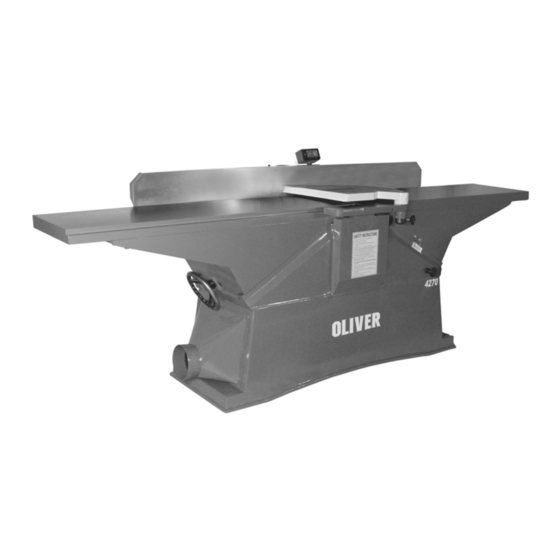
4270 16” Jointer Owner’s Manual Oliver Machinery M-4270 11/2003 Copyright 2003 Seattle, WA info@olivermachinery.net www.olivermachinery.net... -
Page 2: Warranty
Read this manual thoroughly before operating the machine. Oliver Machinery disclaims any liability for machines that have been altered or abused. Oliver Machinery reserves the right to effect at any time, without prior notice, those alterations to parts, fittings, and accessory equipment which they may deem necessary for any reason whatsoever. -
Page 3: Numbe Of Knives (Spiral)
! WARNING Read this manual completely and observe all warning labels on the machine. Oliver Machinery has made every attempt to provide a safe, reliable, easy-to-use piece of machinery. Safety, however, is ultimately the responsibility of the individual machine operator. As with any piece of machinery, the operator must exercise caution, patience, and common sense to safely run the machine. -
Page 4: Number Of Knives (Straight)
16. Misuse: Do not use this Oliver jointer for other than its intended use. If used for other purposes, Oliver disclaims any real or implied warranty and holds itself harmless for any injury or damage which may result from that use. -
Page 5: Table Of Contents
Stock No.(7.5HP, 3PH, 220/440 Volt, pre-wired 220 Volt) .............. 4270.002 Stock No.(5HP, 1PH, 220 volt, spiral head)..................4270.101 Stock No (7.5HP, 3PH, 220/440 volt, pre-wired 220 Volt, spiral head) ........... 4270.102 Infeed Table Travel (in.) ..........................1 Cutterhead speed (RPM) ........................6000 Number of Knives (Straight).......................... -
Page 6: Warnings
Oliver 4270 – 16” Jointer Contents: 1. 16” Jointer 2. Two push blocks 3. Knife setting jig 4. Allen keys 5. Wrenches Uncrating the Machine Uncrate the machine and inspect the unit for signs of shipping damage. If damage is found, contact your dealer immediately. -
Page 7: Dust Collection
Dust Collection The 6” dust collection port (A, Figure 4) is located below the outfeed table. Typically flex hose is used to run from this point to a central trunk line. Note: Do not operate the jointer without dust collection. Electrical Connections ... -
Page 8: Fence
Fence ! WARNING Never make any adjustments with the machine running! Installation of the Fence The fence, although completely assembled, requires bolting to the machine as well as alignment. 1. Mount the fence (Figure 5) to the machine base (Figure 4) lining up the holes (A), using the allen bolts provided. -
Page 9: Knives
Knives ! WARNING The knives are extremely sharp. Use caution when handling. Installation of the Knives 1. To expose the cutterhead, move the fence all the way back. 2. Back down both the infeed and outfeed tables to their lowest position. Be sure to loosen the lock on the outfeed table before doing so. -
Page 10: Adjusting The Outfeed Table
Adjusting the Outfeed Table 1. Once the knives are set it is now time to set the outfeed table. For proper operation the height of the outfeed table must be set to the highest point of the cutting circle. To do this, set a straight edge on the outfeed table as shown in Figure 10. -
Page 11: Jointing
Jointing In order to craft a good woodworking project, it is necessary to have a square piece of wood to start with. The way to do this is with a jointer. You need one straight edge and one flat face. After you have these, you can plane to thickness and rip to width and the resulting piece will be square and true on all four sides. -
Page 12: Beveling
Beveling For beveling (Figure 16), set the fence to the desired angle using a protractor and lock into place. Feed the material through pressing firmly against the fence and tables. Several passes may be necessary for the desired result. Rabbeting ! WARNING Rabbeting requires removal of the blade guard. -
Page 13: Maintenance
Maintenance V-Belts After the first 20 hours of operation it is necessary to check the tension on of the V- belts. To do this, open the access door (A, Figure 19). With medium finger pressure the belt should push in approximately ½” about midway between the pulleys. -
Page 14: Troubleshooting
Troubleshooting Description of Symptoms Possible Cause Corrective Action 1. Fuse blown or circuit breaker 1. Replace fuse or reset circuit tripped breaker 2. Cord Damaged 2. Have cord replaced 3. Faulty switch 3. Replace switch Machine will not start 4. Not connected power 4.
Need help?
Do you have a question about the 4270 and is the answer not in the manual?
Questions and answers