FS S5810 Series Hardware Installation And Maintenance Manual
Hide thumbs
Also See for S5810 Series:
- Quick start manual (66 pages) ,
- Quick start manual (19 pages) ,
- Quick start manual (53 pages)

Related Manuals for FS S5810 Series


Summary of Contents for FS S5810 Series
- Page 1 S5810 Series Switches Hardware Installation and Maintenance Guide V1.0.2306A Innovation · Expertise · Agility...
- Page 2 Safety Statement: • To avoid harm to people and equipment, please read the safety recommendations in the Safety Precautions for FS Switches before installing the FS Switch. Verify that the requirements described in the Safety Precautions for FS •...
-
Page 3: Table Of Contents
Contents 1. Hardware Installation and Parts Replacement 1.1 Installation Procedure 1.2 Installation Preparation 1.3 Installing a Switch 1.4 Installing Modules 1.5 Connecting a Switch 1.6 Post-Installation Checks 1.7 System Commissioning 1.8 Parts Replacement 2. Troubleshooting After Installatio 2.1 Troubleshooting Flowchart 2.2 Guide to Using Switches Innovation ·... -
Page 4: Hardware Installation And Parts Replacement
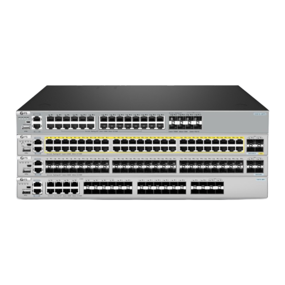
The S5810 series switches provide flexible media interfaces to meet the connectivity needs of different media in network construction. Innovation · Expertise · Agility... -
Page 5: Installation Procedure
Hardware Installation and Parts Replacement Switch Hardware Installation and Maintenance Guide 1.1 Installation Procedure Mounting the Connecting Installation Preparation Installing a Rack system grounding switch in the rack Inserting various types Connecting the interface cables or Connecting power of modules optical cables for each module supply bundling the cables and optical cable... - Page 6 Replacement Switch Hardware Installation and Maintenance Guide 1.2.2 Checking the Installation Site The S5810 series switches must be used indoors. To ensure normal operations and long service life of the device, the installation site must meet the following requirements. Requirement...
- Page 7 Hardware Installation and Parts Replacement Switch Hardware Installation and Maintenance Guide 1.2.3 Mounting the Cabinet or Rack When mounting the cabinet, please note the following: All expansion bolts for fastening the cabinet base to the ground should be installed and tightened in •...
-
Page 8: Installing A Switch
1.3.1 Mounting the Switch in a Cabinet or Rack The S5810 series switches can be installed in a standard 19-inch four-post EIA rack. Mount the switch on the rack with the front panel facing forward; for safety reasons, fasten the randomly... -
Page 9: Installing Modules
Hardware Installation and Parts Replacement Switch Hardware Installation and Maintenance Guide 1.3.2 Mounting the Switch on a Workbench In most cases, users do not have a standard 19-inch rack. Therefore, the most common method is to place the switch on a clean workbench. This operation is relatively simple, and the specific installation process is as follows:... - Page 10 Hardware Installation and Parts Replacement Switch Hardware Installation and Maintenance Guide Installing the U1D-H10070-DRB power module. Remove the new power module from the packaging box and confirm that the input mode and input specifications of the power module match the requirements. Remove the power module bracket.
- Page 11 Hardware Installation and Parts Replacement Switch Hardware Installation and Maintenance Guide Remove the U1D-H10070-DRB power module Press the latch on the module and grasp the handle with one hand. Place your other hand under the module tosupport its weight. Pull the power module out of the slot gently. Install the filler panel in the empty slot.
-
Page 12: Connecting A Switch
Hardware Installation and Parts Replacement Switch Hardware Installation and Maintenance Guide 1.5 Connecting a Switch 1.5.1 Connecting Power Cables Precautions: • To avoid electric shock, do not connect the power cable while the power is on. • Before connecting cables, take ESD protection measures, for example, wear ESD gloves or an ESD wrist strap. - Page 13 Hardware Installation and Parts Replacement Switch Hardware Installation and Maintenance Guide 2. Lock the AC power cable with the locking strap. 3. Connect the other end of the AC power cable to the external AC power supply system. - Perform the following steps to connect the DC power cables: Insert the DC power cable plug to the power socket in the DC power module.
- Page 14 Hardware Installation and Parts Replacement Switch Hardware Installation and Maintenance Guide • When inserting an optical module to a port, hold the optical module horizontally. If the optical module cannot be completely inserted into the optical port, do not force it into the port. Turn the optical module 180 degrees over and try again.
- Page 15 Hardware Installation and Parts Replacement Switch Hardware Installation and Maintenance Guide 1.5.5 Connecting High-speed Cables • Before connecting cables, take ESD protection measures, for example, wear ESD gloves or an ESD wrist strap. • Both ends of an idle high-speed cable must be covered by an ESD cap. •...
- Page 16 Connecting the Grounding Cable There is one ground terminal on the back of the S5810 Series switches chassis, which should be connected to the grounding lug of the rack first, and then connect the grounding lug to the grounding bar of the equipment room.
-
Page 17: Post-Installation Checks
1.5.7 Connecting the Console Port Connection Steps: Connect the RJ45 connector of an Ethernet cable to the console port of the switch, and connect the DB9 connector to a network management switch or terminal. • By default, the baud rate is 9600, data bit 8, parity check none, stop bit 1, and flow control none. 1.6 Post-Installation Checks •... -
Page 18: System Commissioning
Hardware Installation and Parts Replacement Switch Hardware Installation and Maintenance Guide 1.7 System Commissioning 1.7.1 Setting Up the Configuration Environment Connect the PC to the console port of the switch through the Ethernet cable, as shown in the figure below. Figure 11: Configuration Environment Step 1: Connecting the Ethernet Cable... - Page 19 Hardware Installation and Parts Replacement Switch Hardware Installation and Maintenance Guide Step 4: Setting Terminal Parameters Parameter requirements: Baud rate is 9600, connection type is Serial, fill in COM port number according to the actual situation. The specific diagram is as follows. Figure 12: Setting Terminal Parameters Innovation ·...
-
Page 20: Parts Replacement 1
Hardware Installation and Parts Replacement Switch Hardware Installation and Maintenance Guide Step 5: Once the serial port parameters are set, click <Open> to enter the CLI interface 1.8 Parts Replacement 1.8.1 Removing a Power Module Removing the PSM-C70WAC or PSM-C150WAC Power Module: Press the latch on the module and grasp the handle with one hand. - Page 21 Hardware Installation and Parts Replacement Switch Hardware Installation and Maintenance Guide • Ensure that the new optical module has the same center wavelength and complies with the same standards as the old one. After removing the optical fibers from an optical module, cover the fiber connectors with dust caps. •...
- Page 22 Hardware Installation and Parts Replacement Switch Hardware Installation and Maintenance Guide Figure 15: MPO Connector 4. Pull out the optical module, plug the dustproof plug and dispose of it. - There are two types of buckles on the optical module. A pull-rod handle that needs to be turned over to open, as shown in Figure 16.
- Page 23 Hardware Installation and Parts Replacement Switch Hardware Installation and Maintenance Guide 5. Take out the new optical module from the package, and slowly insert it into the interface until you hear a "pop" sound, indicating that it has been installed in place. 6.
-
Page 24: Troubleshooting After Installation
Troubleshooting After Installation Innovation · Expertise · Agility... -
Page 25: Troubleshooting Flowchart
Check the connector of power supply module each module Check the installation of Check the LEDs on the device other modules Check serial port connection Check the cable connection and parameters Contact FS Technical Support Innovation · Expertise · Agility... -
Page 26: Guide To Using Switches
Fault Symptom The login password is forgotten. Handling Method Contact FS technical support. Fault 2: The AC power module does not work Fault Symptom All LEDs on the front panel are off. The fan status LED is off, and the fan does not rotate. The power supply status LED is off. - Page 27 First confirm whether the module is inserted in place. If everything is normal, but the newly inserted module still can not be powered on and works, please contact FS technical support. Fault 7: The link can not be set up between optical ports Fault Symptom The system runs normally.
- Page 28 FS has invested resources in product R&D, quality control, intelligent manufacturing, industry-leading experts, professional technical support, and networking solutions. All is to provide customers with higher-performance, lower-power consumption, and the most cost-effective products, promoting clients' network upgrades. For more information and technical support, welcome to contact us at www.fs.com/contact_us...
Need help?
Do you have a question about the S5810 Series and is the answer not in the manual?
Questions and answers