FS S5810 Series Quick Start Manual
Managed l3 enterprise switches
Hide thumbs
Also See for S5810 Series:
- Quick start manual (66 pages) ,
- Hardware installation and maintenance manual (28 pages) ,
- Quick start manual (19 pages)
Table of Contents
Advertisement
Available languages
Available languages
Quick Links
CON SOL E
STAT USPW
1
R1 PWR2 MGM
2
3
T
4
5
6
MINI CON SOLE
MG MT
CON SOL E
STAT USPW
1
2
R1 PWR2 MGM
3
T
4
5
6
PoE
MINI CON SOLE
MG MT
S58 10- 48T S
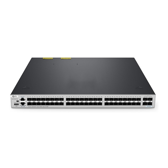
S5810 Series Switches
MANAGED L3 ENTERPRISE SWITCHES
MANAGED L3 ENTERPRISE SWITCHES
SWITCHS MANAGEABLES L3 POUR ENTREPRISES
Quick Start Guide
Quick Start Anleitung
Guide de Démrrage Rapide
7
8
9
10
11
12
13
14
15
16
17
18
19
20
21
22
23
24
25
7
8
9
10
11
12
13
14
15
16
17
18
19
20
21
22
23
24
25
26
V1.0
26
27
28
25F
SFP +
26F
27F
28F
29F
30F
31F
32F
27
28
29
30
31
32
33
34
35
36
37
38
39
40
41
42
43
44
45
46
S58 10- 28T S
SFP +
47
48
49F
50F
51F
52F
Advertisement
Table of Contents

Subscribe to Our Youtube Channel
Related Manuals for FS S5810 Series


Summary of Contents for FS S5810 Series
- Page 1 CON SOL E STAT USPW R1 PWR2 MGM MINI CON SOLE MG MT S58 10- 48T S SFP + S5810 Series Switches MANAGED L3 ENTERPRISE SWITCHES MANAGED L3 ENTERPRISE SWITCHES SWITCHS MANAGEABLES L3 POUR ENTREPRISES Quick Start Guide V1.0 Quick Start Anleitung...
- Page 2 Introduction Thank you for choosing S5810 Series Switches. This guide is designed to familiarize you with the layout of the S5810 Series Switches and describes how to deploy them in your network. On=Link Flashing=ACT SFP+ S5810-28TS CONSOLE STATUS PWR1 PWR2 MGMT...
-
Page 3: Hardware Overview
S5810-48TS Power Cord x2 USB Cable x1 Grounding Cable x1 Rubber Pad x4 Mounting Bracket x2 M4 Screw x8 Hardware Overview S5810-28TS Front Panel Ports MINI CONSOLE SFP+ CONSOLE SFP+ On=Link Flashing=ACT S5810-28TS CONSOLE STATUS PWR1 PWR2 MGMT MINI CONSOLE MGMT On=Link Flashing=ACT Green=1000M Yellow=10/100M Green=1000M Yellow=100M... - Page 4 Front Panel LEDs PWR1 MGMT SFP+ On=Link Flashing=ACT SFP+ S5810-28TS CONSOLE STATUS PWR1 PWR2 MGMT MINI CONSOLE MGMT Green=1000M Yellow=100M | Green=10G/1G On=Link Flashing=ACT Green=1000M Yellow=10/100M status PWR2 RJ45 State Description Off The switch is powered off. Blinking Green The switch is initializing. The LED blinking frequency is 3Hz. If the (3Hz) LED keeps blinking, the switch is abnormal.
- Page 5 Solid Yellow The RJ45 Ethernet port is linking up at 100/10M. RJ45 The RJ45 Ethernet port is receiving and delivering data at Blinking Yellow 100/10M. Off The SFP port is not linked. Solid Green The SFP port is linking up at 1000M. Blinking Green The SFP port is receiving and delivering data at 1000M.
- Page 6 Ports Description MINI CONSOLE A serial port for installing the software driver. CONSOLE A RJ45 console port for serial management. A USB management port for software and configuration backup and offline software upgrade. MGMT An out-of-band Ethernet management port. RJ45 10/100/1000Base-T ports for Ethernet connection.
-
Page 7: Installation Requirements
Off The MGMT port is not linked. Solid Green The MGMT port is linking up at 1000M. Blinking Green The MGMT port is receiving and delivering data at 1000M. MGMT Solid Yellow The MGMT port is linking up at 100/10M. Blinking Yellow The MGMT port is receiving and delivering data at 100/10M. -
Page 8: Site Environment
Site Environment Make sure that the temperature of installation site is maintained at 0°C~50°C. Make sure that the relative humidity of installation site is maintained at 10%~90%. The installation site must be free from leaking, dripping water or heavy dew. Keep the installation site dust-free. -
Page 9: Rack Mounting
Rack Mounting CO NS OL E STA TUS PW R1 PW R2 MG MT CO M BO MI NI CO NS OL SF P+ 29 F 30 F 31 F 32 F S5 81 0- 28 TS M GM T On =L in k Fla sh in g= AC T Gr ee n= 10 00... -
Page 10: Wall Mounting
Wall Mounting M od ul e1 SF P+ 30 F 31 F 32 F S5 81 0- 28 TS 1. Fix the mounting brackets to the two sides of the switch with eight M4 screws. 2. Use the expansion screws to securely attach the mounting brackets on the wall. -
Page 11: Installing The Power Supply Module
Installing the Power Supply Module M od ul e2 PW R1 PW R1 PW R2 1. Take a new power module out of the package and confirm the input mode and the input parameters of the power module match the requirements. 2. -
Page 12: Grounding The Switch
Grounding the Switch M od ul e1 M od ul e2 PW R1 1. Connect one end of the grounding cable to a proper earth ground, such as the rack in which the switch is mounted. 2. Fix the grounding lug to the grounding point on the back panel of the switch with the washers and screws. - Page 13 1. Plug the AC power cord into the power port on the back panel of the switch. 2. Connect the other end of the power cord to an AC power source. WARNING: Do not install power cord while the power is on. Connecting the RJ45 Ports PW R2 1.
-
Page 14: Connecting The Console Port
1. Plug the compatible SFP/SFP+ optical module into the SFP/SFP+ port. 2. Connect one end of a fiber optic cable to the optical module. Then connect the other end of the cable to another fiber device. WARNING: Laser beams will cause eye damage. Do not look into bores of optical modules or fiber optical cables without eye protection. -
Page 15: Stacking The Switches
On=Link Flashing=ACT Green=1000M Yellow=10/100M Green=1000M Yellow=100M Green=10G/1G The S5810 series switches support stacking up to 8 switches between the same series together. The switch can be physically stacked using optical fiber cables connected to SFP+ transceivers or 10G Direct Attach Cables (DAC). Only four SFP+ uplinks on the switch can be used for physical stacking. - Page 16 Step 3: Open a browser, type http://192.168.1.1, and enter the default username and password, admin/admin. IE 8/9/10/11, Google Chrome, Firefox are supported admin ***** Login Step 4: Click Login to display the web-based configuration page. Configuring the Switch via the Console Port Step 1: Connect a computer to the switch's console port using the console cable.
-
Page 17: Troubleshooting
Troubleshooting The Power Module Cannot Supply Power All indicators on the front panel of the switch are off. The status indicator of the fan module is off. The indicator on the panel of the power module is off. The fan does not work. First disconnect the power cord of the power module, then check the following: 1. -
Page 18: Online Resources
Contact Us https://www.fs.com/contact_us.html Product Warranty Warranty: The S5810 series switches enjoy 3 years limited warranty against defect in materials or workmanship. For more details about warranty, please check at https://www.fs.com/policies/warranty.html Return: If you want to return item(s), information on how to return can be found at... - Page 19 Einführung Vielen Dank, dass Sie sich für Switches der Serie S5810 entschieden haben. Diese Anleitung soll Sie mit dem Aufbau der S5810 Series Switches vertraut machen und erklärt, wie Sie sie in Ihrem Netzwerk einsetzen können. On=Link Flashing=ACT SFP+ S5810-28TS...
- Page 20 S5810-48TS Netzkabel x2 USB-Kabel x1 Erdungskabel x1 Gummipad x4 Montagehalterung x2 M4-Schraube x8 Hardware-Übersicht S5810-28TS Ports an der Vorderseite MINI CONSOLE SFP+ CONSOLE SFP+ On=Link Flashing=ACT S5810-28TS CONSOLE STATUS PWR1 PWR2 MGMT MINI CONSOLE MGMT On=Link Flashing=ACT Green=1000M Yellow=10/100M Green=1000M Yellow=100M Green=10G/1G RJ45 USB MGMT...
- Page 21 LEDs an der Vorderseite PWR1 MGMT SFP+ On=Link Flashing=ACT SFP+ S5810-28TS CONSOLE STATUS PWR1 PWR2 MGMT MINI CONSOLE MGMT Green=1000M Yellow=100M | Green=10G/1G On=Link Flashing=ACT Green=1000M Yellow=10/100M status PWR2 RJ45 Status Beschreibung Der Switch ist ausgeschaltet. Blinkt Grün Der Switch wird initialisiert. Die Blinkfrequenz der LED beträgt 3 (3Hz) Hz.
- Page 22 Durchgehend Der RJ45-Ethernet-Port ist mit 100/10M verbunden. Gelb RJ45 Der RJ45-Ethernet-Port empfängt und überträgt Daten mit Blinkt Gelb 100/10M. Der SFP-Port ist nicht verbunden. Durchgehend Der SFP-Port ist mit 1000M verbunden. Grün Blinkt Grün Der SFP-Port empfängt und überträgt Daten mit 1000M. Durchgehend Der SFP-Port ist mit 100M verbunden.
- Page 23 Ports Beschreibung MINI CONSOLE Ein serieller Port für die Installation des Softwaretreibers. CONSOLE Ein RJ45-Console-Port für die serielle Verwaltung. Ein USB-Verwaltungsport für Software- und Konfigurationsbackups und Offline- Softwareupgrades. MGMT Ein Out-of-Band-Ethernet-Verwaltungsport. RJ45 10/100/1000Base-T-Ports für den Ethernet-Anschluss. SFP+ SFP+-Ports für 1/10G-Verbindungen. LEDs an der Vorderseite PWR1 MGMT SFP+...
- Page 24 Der MGMT-Port ist nicht verbunden. Durchgehend Der MGMT-Port ist mit 1000M verbunden. Grün Blinkt Grün Der MGMT-Port empfängt und sendet Daten mit 1000M. MGMT Durchgehend Der MGMT-Port ist mit 100/10M verbunden. Gelb Blinkt Gelb Der MGMT-Port empfängt und sendet Daten mit 100/10M. Der RJ45-Ethernet-Port ist nicht verbunden.
-
Page 25: Montage Des Switches
Standortumgebung Achten Sie darauf, dass die Temperatur am Aufstellungsort zwischen 0°C und 50°C gehalten wird. Achten Sie darauf, dass die relative Luftfeuchtigkeit am Aufstellungsort zwischen 10 und 90% liegt. Der Aufstellungsort muss frei von austretendem, tropfenden Wasser oder starkem Tau sein. Halten Sie den Aufstellungsort staubfrei. - Page 26 Rack-Montage CO NS OL E STA TUS PW R1 PW R2 MG MT CO M BO MI NI CO NS OL M GM T On =L in k Fla SF P+ sh in g= AC T Gr ee n= 10 00 29 F M Ye llo w= 30 F...
- Page 27 Wandmontage M od ul e1 SF P+ 30 F 31 F 32 F S5 81 0- 28 TS 1. Befestigen Sie die Montagehalterungen mit M4-Schrauben an den beiden Seiten des Switches. 2. Verwenden Sie die Erweiterungsschrauben, um die Montagehalterungen sicher an der Wand zu befestigen.
- Page 28 Installation des Stromversorgungsmoduls M od ul e2 PW R1 PW R1 PW R2 1. Nehmen Sie ein neues Stromversorgungsmodul aus der Verpackung und prüfen Sie, ob der Eingangsmodus und die Eingangsparameter des Stromversorgungsmoduls den Anforderungen entsprechen. 2. Entfernen Sie das alte Stromversorgungsmodul und nehmen Sie die mit Leistungsinformationen bedruckte Fläche als Oberseite des Stromversorgungsmoduls.
-
Page 29: Anschließen Der Stromversorgung
Erdung des Switches M od ul e1 M od ul e2 PW R1 1. Schließen Sie ein Ende des Erdungskabels an eine geeignete Erdung an, z. B. an das Rack, in dem der Switch montiert ist. 2. Befestigen Sie die Erdungslasche mit den Unterlegscheiben und Schrauben an dem Erdungspunkt auf der Rückseite des Switches. - Page 30 1. Stecken Sie das Netzkabel in den Netzanschluss an der Rückseite des Switches. 2. Schließen Sie das andere Ende des Netzkabels an eine Netzstromquelle an. WARNING: Schließen Sie das Netzkabel nicht an, wenn das Gerät eingeschaltet ist. Anschließen der RJ45-Ports PW R2 1.
- Page 31 1. Stecken Sie das kompatible optische SFP/SFP+-Modul in den SFP/SFP+-Port. 2. Schließen Sie ein Ende eines Glasfaserkabels an das optische Modul an. Schließen Sie dann das andere Ende des Kabels an ein anderes Glasfasergerät an. WARNUNG: Laserstrahlen können zu Augenschäden führen. Schauen Sie nicht ohne Augenschutz in die Bohrungen von optischen Modulen oder Glasfasern.
- Page 32 Stacking der Switches SFP+ On=Link Flashing=ACT S5810-28TS CONSOLE STATUS PWR1 PWR2 MGMT MINI CONSOLE MGMT On=Link Flashing=ACT Green=1000M Yellow=10/100M Green=1000M Yellow=100M Green=10G/1G On=Link Flashing=ACT SFP+ S5810-28TS CONSOLE STATUS PWR1 PWR2 MGMT MINI CONSOLE MGMT On=Link Flashing=ACT Green=1000M Yellow=10/100M Green=1000M Yellow=100M Green=10G/1G On=Link Flashing=ACT SFP+...
- Page 33 I nter net Pro tocol Ver si o n 4 ( TC P / I P v4) Prop er t i es General Yo u c a n g e t I P s e t t i n g s a s s i g n e d a u t o m a t i c a l l y i f y o u r n e t w o r k s u p p o r t s t h i s c a p a b i l i t y .
- Page 34 Konfigurieren des Switches über den Console-Port Schritt 1: Schließen Sie einen Computer über das Console-Kabel an den Console-Port des Switches an. Schritt 2: Starten Sie die Terminalsimulationssoftware wie z. B. HyperTerminal auf dem Computer. Schritt 3: Stellen Sie die Parameter von HyperTerminal ein: 9600 Bits pro Sekunde, 8 Datenbits, keine Parität, 1 Stoppbit und keine Flusskontrolle.
-
Page 35: Fehlersuche
Fehlersuche Das Leistungsmodul liefert keinen Strom Alle Anzeigen auf der Vorderseite des Switches sind ausgeschaltet. Die Statusanzeige des Lüftermoduls ist ausgeschaltet. Die Anzeige auf dem Bedienfeld des Leistungsmoduls ist ausgeschaltet. Der Lüfter funktioniert nicht. Ziehen Sie zunächst das Netzkabel des Netzmoduls ab und überprüfen Sie dann Folgendes: 1. - Page 36 Online Ressourcen Download https://www.fs.com/de/products_support.html Hilfecenter https://www.fs.com/de/service/fs_support.html Kontakt https://www.fs.com/de/contact_us.html Produktgarantie Garantie: Für die Switches der Serie S5810 gilt eine beschränkte Garantie von 3 Jahren auf Material- und Verarbeitungsfehler. Weitere Einzelheiten zur Garantie finden Sie unter: https://www.fs.com/de/policies/warranty.html Rückgabe: Wenn Sie einen oder mehrere Artikel zurückgeben möchten, finden Sie Informationen zur Rückgabe unter...
- Page 37 Introduction Merci d'avoir choisi le Switch de Série S5810. Ce guide est conçu pour vous puissiez vous familiariser avec la configuration du Switch et décrit comment procéder à son déploiement. On=Link Flashing=ACT SFP+ S5810-28TS CONSOLE STATUS PWR1 PWR2 MGMT S5810-28TS MINI CONSOLE MGMT Green=1000M Yellow=100M...
-
Page 38: Aperçu Du Matériel
S5810-48TS Câble d'Alimentation x2 Câble USB x1 Câble de Mise à la Terre x1 Pad en Caoutchouc x4 Support de Montage x2 Vis M4 x8 Aperçu du Matériel S5810-28TS Ports du Panneau Frontal MINI CONSOLE SFP+ CONSOLE SFP+ On=Link Flashing=ACT S5810-28TS CONSOLE STATUS PWR1 PWR2 MGMT... - Page 39 Indicateurs LED du Panneau Frontal PWR1 MGMT SFP+ On=Link Flashing=ACT SFP+ S5810-28TS CONSOLE STATUS PWR1 PWR2 MGMT MINI CONSOLE MGMT Green=1000M Yellow=100M | Green=10G/1G On=Link Flashing=ACT Green=1000M Yellow=10/100M status PWR2 RJ45 Statut Description Éteint Le switch est éteint. Le switch est en cours d'initialisation. La fréquence de Vert Clignotant clignotement de la LED est de 3Hz.
- Page 40 Jaune Le port Ethernet RJ45 est relié à 100/10M. RJ45 Jaune Le port Ethernet RJ45 reçoit et transmet des données à 100/10M. Clignotant Éteint Le port SFP n'est pas relié. Vert Le port SFP est relié à 1000M. Vert Clignotant Le port SFP reçoit et transmet des données à 1000M. Jaune Le port SFP se connecte à...
- Page 41 Ports Description MINI CONSOLE Un port série pour installer le pilote du logiciel. CONSOLE Un port console RJ45 pour la gestion en série. Un port de gestion USB pour la sauvegarde de la configuration du logiciel et la mise à niveau du logiciel hors ligne. MGMT Un port de gestion Ethernet hors bande.
-
Page 42: Exigences D'installation
Éteint Le port MGMT n'est pas relié. Vert Le port MGMT est relié à 1000Mbps. Vert Clignotant Le port SFP reçoit et transmet des données à 1000M. MGMT Jaune Le port MGMT est relié à 100/10M. Jaune Le port MGMT reçoit et transmet des données à 100/10M. Clignotant Éteint Le port Ethernet RJ45 n'est pas relié. - Page 43 Site de l'Installation Ne pas installer l'appareil dans un endroit où la température ambiante dépasse 50°C. Veillez à ce que l'humidité relative du site soit maintenue entre 10 % et 90 %. Le site d'installation doit être exempt de fuites d'eau ou d'humidité. Le site d'installation doit être bien ventilé.
-
Page 44: Montage En Rack
Montage en Rack CO NS OL E STA TUS PW R1 PW R2 MG MT CO M BO MI NI CO NS OL M GM T On =L in k Fla sh in g= AC T Gr ee n= 10 00 M Ye llo w= 10 /1 00 M SF P+... -
Page 45: Montage Mural
Montage Mural M od ul e1 SF P+ 30 F 31 F 32 F S5 81 0- 28 TS 1. Fixez les supports de montage sur les deux côtés du switch à l'aide des vis M4 fournies. 2. Utilisez les vis d'expansion pour fixer solidement les supports de montage sur le mur. -
Page 46: Installation Du Module D'alimentation
Installation du Module d'Alimentation M od ul e2 PW R1 PW R1 PW R2 1. Sortez un nouveau module d'alimentation de son emballage et confirmez que le mode et les paramètres d'entrée du module d'alimentation correspondent aux exigences. 2. Retirez l'ancien module d'alimentation et prenez le plan imprimé avec les informations d'alimentation comme panneau supérieur du module d'alimentation. -
Page 47: Connexion De L'alimentation
Mise à la Terre du Switch M od ul e1 M od ul e2 PW R1 1. Connectez une extrémité du câble de mise à la terre à une mise à la terre appropriée, telle que le rack dans lequel le switch est installé. 2. - Page 48 1. Branchez le câble d'alimentation CA dans le port d'alimentation situé sur le panneau arrière du switch. 2. Connectez l'autre extrémité du câble d'alimentation à une source de courant alternatif. AVERTISSEMENT: Ne pas brancher le câble d'alimentation lorsque l'appareil est sous tension. Connexion des Ports RJ45 PW R2 1.
- Page 49 1. Branchez le module optique SFP/SFP+ compatible dans le port SFP/SFP+. 2. Connectez une extrémité d'un câble en fibre optique au module. Puis connectez l'autre extrémité du câble à un autre dispositif à fibre. AVERTISSEMENT: Les faisceaux laser peuvent causer des lésions oculaires. Ne pas regarder directement dans les orifices des modules optiques ou des câbles à...
- Page 50 Empilage des Switchs On=Link Flashing=ACT SFP+ S5810-28TS CONSOLE STATUS PWR1 PWR2 MGMT MINI CONSOLE MGMT On=Link Flashing=ACT Green=1000M Yellow=10/100M Green=1000M Yellow=100M Green=10G/1G On=Link Flashing=ACT SFP+ S5810-28TS CONSOLE STATUS PWR1 PWR2 MGMT MINI CONSOLE MGMT On=Link Flashing=ACT Green=1000M Yellow=10/100M Green=1000M Yellow=100M Green=10G/1G On=Link Flashing=ACT SFP+...
- Page 51 Étape 3 : Ouvrez un navigateur, tapez http://192.168.1.1, et entrez le nom d'utilisateur et le mot de passe par défaut, admin/admin. IE 8/9/10/11, Google Chrome, Firefox are supported admin ***** Login Étape 4: Cliquez sur Login pour afficher la page de configuration basée sur le Web. Configuration du Switch via le Port Console Étape 1: Connectez un ordinateur au port de console du switch à...
-
Page 52: Dépannage
Dépannage Le Module d'Alimentation ne Fournit pas de Courant Tous les indicateurs du panneau frontal du switch sont éteints. L'indicateur d'état du module de ventilation est éteint. L'indicateur sur le panneau du module d'alimentation est éteint. Le ventilateur ne fonctionne pas. Débranchez d'abord le câble d'alimentation du module d'alimentation, puis vérifiez les points suivants : 1. -
Page 53: Garantie Du Produit
Informations en Ligne Téléchargez https://www.fs.com/fr/products_support.html Centre d'Assistance https://www.fs.com/fr/service/fs_support.html Contactez-Nous https://www.fs.com/fr/contact_us.html Garantie du Produit Garantie: Les switchs de Série S5810 bénéficient d'une garantie limitée de 3 ans contre tout défaut matériel ou de fabrication. Pour plus de détails sur la garantie, veuillez consulter la page https://www.fs.com/fr/policies/warranty.html... -
Page 54: Compliance Information
Any changes or modifications not expressly approved by the grantee of this device could void the user's authority to operate the equipment. Responsible party (only for FCC matter) FS.COM Inc. 380 Centerpoint Blvd, New Castle, DE 19720, United States https://www.fs.com... - Page 55 EU konform ist. Eine Kopie der EU-Konformitätserklärung finden Sie unter www.fs.com/de/company/quality_control.html. FS.COM GmbH déclare par la présente que cet appareil est conforme à la Directive 2014/30/UE et 2014/35/UE. Une copie de la Déclaration UE de Conformité est disponible sur https://www.fs.com/fr/company/quality_control.html FS.COM LIMITED...
- Page 56 Q.C. PASSED Copyright © 2022 FS.COM All Rights Reserved.
Need help?
Do you have a question about the S5810 Series and is the answer not in the manual?
Questions and answers