FS S5860-20SQ Quick Start Manual
Managed l2/l3 enterprise switch
Hide thumbs
Also See for S5860-20SQ:
- Configuration manual (8 pages) ,
- Quick start manual (24 pages) ,
- Quick start manual (57 pages)
Table of Contents
Advertisement
Advertisement
Table of Contents

Related Manuals for FS S5860-20SQ


Summary of Contents for FS S5860-20SQ
- Page 1 S5860-20SQ MANAGED L2/L3 ENTERPRISE SWITCH Quick Start Guide V1.1...
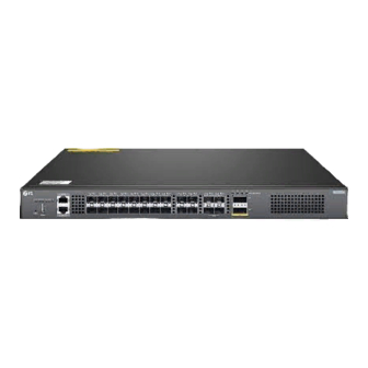
- Page 2 Introduction Thank you for choosing S5860-20SQ Switch. This guide is designed to familiarize you with the layout of the switch and describes how to deploy the switch in your network. S5860-20SQ MGMT 40G Breakout STATUS PWR1PWR2 FAN MGMT ID FUNC...
-
Page 3: Hardware Overview
Hardware Overview Front Panel Ports MGMT SFP+ SFP28 S5860-20SQ 40G Breakout MGMT STATUS PWR1PWR2 FAN MGMT ID FUNC CONSOLE USB CONSOLE QSFP+ Ports Description SFP+ SFP+ ports for 1/10G connection SFP28 SFP28 ports for 10/25G connection QSFP+ QSFP+ ports for 40G or 4x 10G connection... - Page 4 PWR1 PWR2 Grounding Point Fan Slots Dual Power Supplies Front Panel LEDs STATUS/PWR1/PWR2 FAN/MGMT/ID SFP+ SFP28 QSFP+ S5860-20SQ 40G Breakout MGMT STATUS PWR1PWR2 FAN MGMT ID FUNC CONSOLE LEDs Status Description The system is powered o . 1. A system fault occurs.
-
Page 5: Installation Requirements
LEDs Status Description The locator is controlled by CPLD by default. The locator is controlled by O&M personnel Solid Blue remotely. The SFP+ port is NOT connected. Solid Green The SFP+ port is connected at 1/10G. SFP+ The SFP+ port is transmitting or receiving Blinking Green data at 1/10G. -
Page 6: Mounting The Switch
Mounting the Switch Desk Mounting S58 60-2 0SQ 1. Attach four rubber pads to the bottom. 2. Place the chassis on a desk. Rack Mounting 40G Bre ako 40 G 1. Secure the mounting brackets to the two sides of the switch with six M4 screws. -
Page 7: Installing The Power Supply Module
2. Attach the switch to the rack using four M6 screws and cage nuts. Installing the Power Supply Module M 1S FA N I- F M 1S FA N I- F St at us St at us FA N 2 PW R1 PW R2 1. -
Page 8: Grounding The Switch
Grounding the Switch M 1S FA N I- F M 1S FA N I- F FA N 1 St at us 1. Connect one end of the grounding cable to a proper earth ground, such as the rack in which the switch is mounted. - Page 9 Connecting the SFP+ Ports First install SFP+ transceivers and then connect ber optic cables to the transceiver ports, or directly connect DAC cables to the SFP+ slots. Connecting the SFP28 Ports First install SFP28 transceivers and then connect ber optic cables to the transceiver ports.
-
Page 10: Connecting The Console Port
Connecting the QSFP+ Ports First install QSFP+ transceivers and then connect ber optic cables to the transceiver ports, or directly connect DAC cables to the QSFP+ slots. WARNING: Laser beams will cause eye damage. Do not look into bores of optical modules or optical bers without eye protection. - Page 11 Connecting the MGMT Port 1. Connect one end of a standard RJ45 Ethernet cable to a computer. 2. Connect the other end of the cable to the MGMT port on the front of the switch.
- Page 12 Con guring the Switch Con guring the Switch Using the Web-based Interface Step 1: Connect the computer to the Management port of the switch using the network cable. Step 2: Set the IP address of the computer to 192.168.1.x.(“x” is any number from 2 to 254.) I nte r net Protoco l Ver si o n 4 ( TC P / I P v4) Prop er t i es General Yo u c a n g e t I P s e t t i n g s a s s i g n e d a u t o m a t i c a l l y i f y o u r n e t w o r k...
- Page 13 Con guring the Switch Using the Console Port Step 1: Connect a computer to the switch's console port using the console cable. Step 2: Start the terminal simulation software such as HyperTerminal on the computer. Step 3: Set the parameters of the HyperTerminal: 9600 bits per second, 8 data bits, no parity, 1 stop bit and no ow control.
-
Page 14: Troubleshooting
Troubleshooting Power System Fault The indicator on the front panel of host is OFF. The Status indicator of fan module is OFF, and the fan does not work. The indicator on the panel of the power module is OFF and the fan does not work. Please check the following: First disconnect the power cord of the power module. -
Page 15: Support And Other Resources
Contact Us Product Warranty FS ensures our customers that any damage or faulty items due to our workmanship, we will o er a free return within 30 Days from the day you receive your goods. This excludes any custom made items or tailored solutions.
Need help?
Do you have a question about the S5860-20SQ and is the answer not in the manual?
Questions and answers