
Related Manuals for FS S5860 Series


Summary of Contents for FS S5860 Series
- Page 1 S5860 Series Switches Hardware Installation and Maintenance Guide V1 .0 .2306A Innovation · Expertise · Agility...
- Page 2 Preface Audience : This document is for network engineers responsible for installing and maintaining S5860 series switches. Experience with network equipment installation and maintenance is required. Feature Statement: Please visit the FS.COM Technical Documents page to download the datasheet and obtain information on the specifications supported by the product .
-
Page 3: Table Of Contents
Contents 1. Hardware Installation and Parts Replacement 1.1 Installation Procedure 1.2 Installation Preparation 1.3 Installing a Switch 1.4 Installing Modules 1.5 Connecting a Switch 1.6 Post-Installation Checks 1.7 System Commissioning 1.8 Parts Replacement 2. Troubleshooting After Installation 2.1 Troubleshooting Flowchart 2.2 Guide to Using Switches 2.3 Guide to Using Optical Modules Innovation ·... -
Page 4: Hardware Installation And Parts Replacement
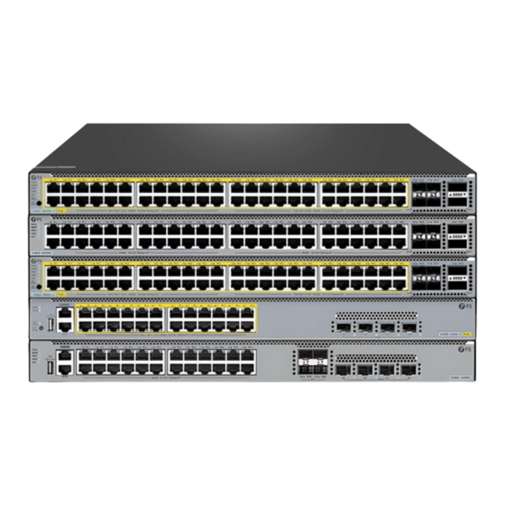
Hardware Installation and Parts Replacement The S5860 series switches, launched by FS.com, are a new generation of Layer 3 switches that integrate high performance, high security, and multiple services. They are primarily used in the convergence layer of campus networks, providing line-speed multi-layer switching and comprehensive QoS (Quality of Service) policies. -
Page 5: Installation Procedure
• The power supply and required current are available on the installation site. • The Ethernet cables have been deployed on the installation site. 1.2.1 Checking the Installation Site The S5860 series switches must be installed indoors.The installation site must meet the following requirements. Table 1: Requirements for the Installation Site... - Page 6 Hardware Installation and Parts Replacement Switch Hardware Installation and Maintenance Guide 1.2.2 Mounting the Cabinet or Rack Precautions When mounting the cabinet, please note the following: • All expansion bolts for fastening the cabinet base to the ground should be installed and tightened in sequence from bottom to up (large flat washer, spring washer, and nut), and the installation holes on the base and the expansion bolts are aligned.
-
Page 7: Installing A Switch
Precautions Before installing the S5860 series switch in a cabinet, please check whether the racks are properly positioned. If the racks are too closeto the front door of the cabinet, you may not be able to close the front door after plugging in the Ethernet and fiber cables .The front panel of the switch should be at least 10 mm (0.39 in.) - Page 8 Mounting the Switch in a Rack The S5860 series switches are designed to meet the EIA standard size and can be installed in a 19-inch rack. During installation, the front panel of the switch should be placed forward on the brackets. It is recommended to use a tray for mounting the S5860 series switch and then secure it to the rack brackets.
-
Page 9: Installing Modules
Hardware Installation and Parts Replacement Switch Hardware Installation and Maintenance Guide 1.3.2 Mounting the Switch on a Workbench In most cases, users do not have a standard 19-inch rack. Therefore, the most common method is to place the switch on. 1. - Page 10 Hardware Installation and Parts Replacement Switch Hardware Installation and Maintenance Guide • Insert the fan module smoothly and steadily. Pay attention to the orientation of the fan panel and ensure it is inserted correctly. • If the module is not aligned properly during insertion, it must be withdrawn and reinserted. •...
- Page 11 Hardware Installation and Parts Replacement Switch Hardware Installation and Maintenance Guide Insert the power module smoothly. When inserting, pay attention to the orientation of the power • panel and ensure it is inserted correctly. • If you encounter resistance or difficulty while inserting, you must retract the module being inserted, recheck the alignment between the power module and the guide rail, and then insert it again.
-
Page 12: Connecting A Switch
1.5.1 Connecting the Grounding Cable There is one ground terminal on the back of the S5860 series switches chassis, which should be connected to the grounding lug of the rack first, and then connect the grounding lug to the grounding bar of the equipment room. - Page 13 Hardware Installation and Parts Replacement Switch Hardware Installation and Maintenance Guide Procedure 1. Wear an anti-static wristband or anti-static gloves. If you wear an anti-static wristband, ensure that one end of the wristband is grounded and the other end has contact with your skin. 2.
- Page 14 Hardware Installation and Parts Replacement Switch Hardware Installation and Maintenance Guide 1.5.4 Connecting Optical Fibers Insert the single-mode or multi-mode fiber into the corresponding interface according to the panel identification, and distinguish the transmit and receive ends of a fiber cable. 1.5.5 Connecting High-speed Cables •...
-
Page 15: Post-Installation Checks
Hardware Installation and Parts Replacement Switch Hardware Installation and Maintenance Guide When disassembling, first gently push the cable connector inwards, then hold the pull ring and pull it outwards. Do not directly pull the cable by gripping the cable connector. Refer to Figure 10 for reference. Figure 10: Removing a High-speed Cable 8. -
Page 16: System Commissioning
Hardware Installation and Parts Replacement Switch Hardware Installation and Maintenance Guide 1.6.2 Verifying Cable Connection Verify that the fiber optic cables and twisted pair cables match the interfaces. • • Confirm that the cable bundling is done correctly. Ensure that the grounding wire specifications and connections are correct. •... - Page 17 Hardware Installation and Parts Replacement Switch Hardware Installation and Maintenance Guide Step 1: Connecting the Ethernet Cable 1. Connect the DB-9 connector of the console cable to the serial port of the PC that will be used for configuring the switch. 2.
- Page 18 Hardware Installation and Parts Replacement Switch Hardware Installation and Maintenance Guide Step 4: Setting Terminal Parameters Parameter requirements: Baud rate is 9600, connection type is Serial, fill in COM port number according to the actual situation. The specific diagram is as follows. Figure 10: Setting Terminal Parameters 1.7.2 Powering On the Switch Checklist before Power-On...
-
Page 19: Parts Replacement
Hardware Installation and Parts Replacement Switch Hardware Installation and Maintenance Guide 1.8 Parts Replacement 1.8.1 Removing a Power Module and Fan Module Removing a Fan Module 1. Loosen the captive screws of the fan module. 2. Grasp the handle and pull the fan module out of the slot gently. 3. - Page 20 Hardware Installation and Parts Replacement Switch Hardware Installation and Maintenance Guide • Slowly and vertically remove the PSM-C150WAC power module. • Install a power slot blanking plate if no power module is installed in the removed position to maintain proper ventilation and prevent dust accumulation in the chassis. 1.8.2 Replacing an Optical Module When replacing the optical module, pay attention to the following requirements: •...
- Page 21 Hardware Installation and Parts Replacement Switch Hardware Installation and Maintenance Guide 2. Before replacing an optical module, determine in which cabinet and chassis the optical module is installed, find the optical module in the chassis, and attach a label to the optical module. Record optical fiber locations on the optical module to be replaced and check whether the labels on the optical fibers are correct and clear.
- Page 22 Hardware Installation and Parts Replacement Switch Hardware Installation and Maintenance Guide There are two types of buckles on the optical module. A pull-rod handle that needs to be turned over to open, as shown in Figure 16. The other is a handle-type handle, which is automatically opened during the process of pulling the handle, as shown in Figure 17.
- Page 23 Hardware Installation and Parts Replacement Switch Hardware Installation and Maintenance Guide Procedures 1. Before replacing the faulty switch, be sure to clearly mark the corresponding relationship between the network cable and the port. 2. Check whether the business is ready for power-off, and save relevant business information. 3.
-
Page 24: Troubleshooting After Installation
Troubleshooting After Installation Innovation · Expertise · Agility... -
Page 25: Troubleshooting Flowchart
Troubleshooting After Installation Switch Hardware Installation and Maintenance Guide 2.1 Troubleshooting Flowchart Innovation · Expertise · Agility... -
Page 26: Guide To Using Switches
Fault Symptom The login password is forgotten. Handling Method Contact FS technical support. Fault 2: The AC power module does not work Fault Symptom All LEDs on the front panel are off. The fan status LED is off, and the fan does not rotate. The power supply status LED is off. - Page 27 Sometimes glitches can appear on these hardware. 5. Contact Vendor Support: If there is still no output on the serial port, please contact FS technical support. Fault 5: The serial port console output is garbled Fault Symptom The serial port console output is garbled.
-
Page 28: Guide To Using Optical Modules
Troubleshooting After Installation Switch Hardware Installation and Maintenance Guide 2. Check whether wavelengths of optical transceivers on both sides are consistent. For example, an optical transceiver with a wavelength of 1310 nm cannot be connected to an optical transceiver of 1550 nm. 3. - Page 29 Troubleshooting After Installation Switch Hardware Installation and Maintenance Guide Figure 18: State of the release handle 1.3.3 EMC Grounding Close the release handle Open the release handle 2.3.3 Measures to Prevent Receptacle Contamination 1. Cleaning tissues must be prepared on site. You need to clean the optical connector before inserting it in the receptacle.
- Page 30 Troubleshooting After Installation Switch Hardware Installation and Maintenance Guide Figure 20: Installing a protective cap If no protective cap is available, use fibers to protect the optical module, as shown in Figure20. Figure 21: Using fibers to protect an optical module 3.
- Page 31 Troubleshooting After Installation Switch Hardware Installation and Maintenance Guide Figure 23: Cleaning a receptacle with a cotton swab When cleaning a receptacle, insert the cotton swab and turn it slowly in the receptacle. Do not use • too much strength because the receptacle may be damaged. 5.
- Page 32 FS has invested resources in product R&D, quality control, intelligent manufacturing, industry-leading experts, professional technical support, and networking solutions. All is to provide customers with higher-performance, lower-power consumption, and the most cost- effective products, promoting clients' network upgrades. For more information and technical support, welcome to contact us at www.fs.com/contact_us...
Need help?
Do you have a question about the S5860 Series and is the answer not in the manual?
Questions and answers