FS S5860 Series Quick Start Manual
Ethernet l3 switches
Hide thumbs
Also See for S5860 Series:
- Quick start manual (24 pages) ,
- Hardware installation and maintenance manual (32 pages)
Table of Contents
Advertisement
Available languages
Available languages
Quick Links
Advertisement
Table of Contents

Related Manuals for FS S5860 Series


Summary of Contents for FS S5860 Series
- Page 1 S5860 SERIES ETHERNET L3 SWITCHES L3 ETHERNET-SWITCHES DER S5860 SERIE SWITCHS ETHERNET L3 DE LA SÉRIE S5860 S����シリーズイーサネットL�スイッチ Quick Start Guide V1.0 Quick-Start Anleitung Guide de Démarrage Rapide クイックスタートガイド...
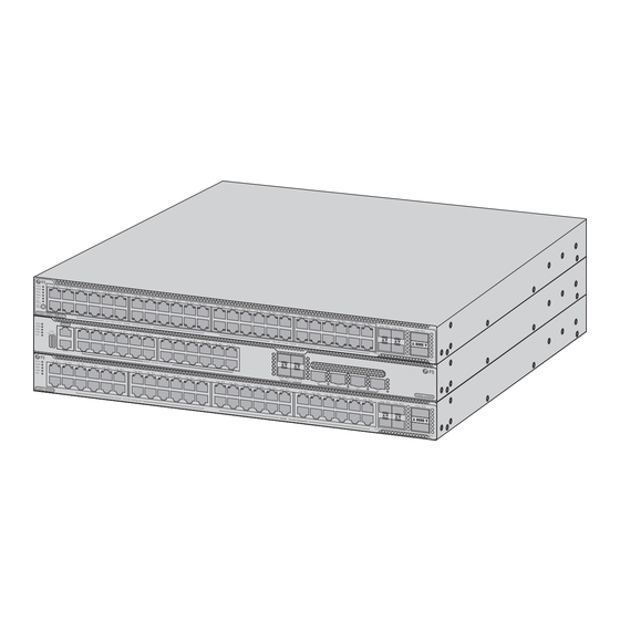
- Page 2 Introduction Thank you for choosing the S5860 Series Ethernet L3 Switches. This guide is designed to familiarize you with the layout of the switches and describes how to deploy them in your network. S5860-48MG-U S5860-24XMG S5860-48XMG Accessories S5860-48XMG/S5860-48MG-U/S5860-24XMG Power Cord x2...
-
Page 3: Hardware Overview
NOTE: 1. The accessories may vary from illustration, please prevail in kind. 2. This power cord cannot be used with other devices, and other power cords should not be used with this device. Hardware Overview Front Panel Ports S5860-48XMG SFP28 RJ45 QSFP+ S5860-48MG-U... -
Page 4: Front Panel Leds
S5860-24XMG CONSOLE SFP+ MGMT RJ45 SFP28 Ports Description Console An RJ45 console port for serial management MGMT An out-of-band Ethernet management port RJ45 100M/1G/2.5G/5G/10G ports for Ethernet connection SFP+ SFP+ ports for 1G/10G connection SFP28 SFP28 ports for 10G/25G connection A USB management port for online upgrade or log storage Front Panel LEDs... - Page 5 S5860-24XMG RJ45 SFP+ Status MGMT PWR1 PWR2 SFP28 LEDs State Description Solid Green The LED indicates the switching status. LED Mode Solid Amber The LED indicates the PoE power supply status. All fan modules are seated and functioning Solid Green properly.
- Page 6 LEDs State Description • Temperature at air inlets or outlets Status Solid Red exceeds the threshold. • The system is faulty. No link is established on this port. S5860-48XMG/ A 1/2.5/5/10Gbps link is established S5860-24XMG on this port. Solid Green A 1/2.5/5Gbps link is established on S5860-48MG-U this port.
- Page 7 Front Panel Button S5860-48MG-U LED Mode Button Description LED Mode Press it for over two seconds to switch the LED mode. Back Panel Ports S5860-48XMG/S5860-48MG-U MGMT M2SFANI-F M2SFANI-F M2SFANI-F MGMT Status Status Status FAN1 FAN2 FAN3 PWR1 PWR2 Console Console USB Ports Description MGMT...
-
Page 8: Installation Requirements
Installation Requirements Before the installation, make sure that you have the following conditions ready: Phillips screwdriver, related bolts and ESD tools. Standard-sized, 19" wide rack with a minimum of 1U height available. Category 5e or higher RJ45 Ethernet cables, ber optic cables, and a console cable. Site Environment Ensure that the temperature of the installation site is maintained at 0°C~45°C. -
Page 9: Mounting The Switch
Mounting the Switch Desk Mounting 1. Attach four rubber pads to the bottom of the switch. 2. Place the switch on a stable desk. NOTE: Do not place heavy objects on the switch. -
Page 10: Rack Mounting
Rack Mounting S5860-48XMG/S5860-48MG-U/S5860-24XMG 1. Secure the front mounting brackets and the sliding rails to the two sides of the switch with screws. 2. Fix the rear mounting brackets to the rack with screws and cage nuts. - Page 11 3. Slide the switch into the rack. 4. Install the switch on the rack with screws and cage nuts. NOTE: Please prepare the screws and cage nuts separately.
-
Page 12: Grounding The Switch
Grounding the Switch M G M T M 2 SF A N I- F M 2 SF A N I- F M 2 SF A N I- F St at us FA N1 St at us FA N2 St at us Co ns ol e FA N3 1. -
Page 13: Connecting The Sfp+ Ports
Connecting the SFP+ Ports PW R1 St at us PW R2 St at us 1. Plug a compatible SFP+ transceiver into the SFP+ port on the switch. 2. Connect a ber optic cable to the ber transceiver. Then connect the other end of the cable to another ber device. -
Page 14: Connecting The Console Port
Connecting the QSFP+ Ports 1. Plug the compatible QSFP+ transceiver into the QSFP+ port on the switch. 2. Connect a ber optic cable to the ber transceiver. Then connect the other end of the cable to another ber device. Connecting the Console Port M G M T M 2 SF A N I- F M 2 SF A N I- F... -
Page 15: Connecting The Usb Port
Connecting the MGMT Port M G M T M 2 SF A N I- F M 2 SF A N I- F St at us FA N1 FA N2 Co ns ol e M G M T M 2 SF A N I- F M 2 SF A N I- F M 2 SF A N I- F St at us... -
Page 16: Connecting The Power
Connecting the Power M 2 SF A N I- F St at us St at us FA N3 PW R1 St at us PW R2 St at us PW R2 St at us 1. Plug the AC power cord into the power port on the switch. 2. -
Page 17: Online Resources
Contact Us Product Warranty FS ensures our customers that for any damage or faulty items due to our workmanship, we will o er a free return within 30 days from the day you receive your goods. This excludes any custom-made items or tailored solutions. - Page 18 Einführung Vielen Dank, dass Sie sich für die L3 Ethernet-Switches der S5860 Serie entschieden haben. Diese Anleitung soll Sie mit dem Aufbau der Switches vertraut machen und beschreibt, wie Sie sie in Ihrem Netzwerk einsetzen können. S5860-48MG-U S5860-24XMG S5860-48XMG Zubehör S5860-48XMG/S5860-48MG-U/S5860-24XMG Netzkabel x2 Erdungskabel x1...
- Page 19 HINWEIS: 1. Bitte beachten Sie, dass das Zubehör von der Abbildung abweichen kann. 2. Dieses Netzkabel kann nicht mit anderen Geräten verwendet werden, und andere Netzkabel sollten nicht mit diesem Gerät verwendet werden. Hardware-Übersicht Ports an der Vorderseite S5860-48XMG SFP28 RJ45 QSFP+ S5860-48MG-U...
-
Page 20: Leds An Der Vorderseite
S5860-24XMG CONSOLE SFP+ MGMT RJ45 SFP28 Ports Beschreibung Console Ein RJ45-Console-Port für die serielle Verwaltung MGMT Ein Out-of-Band-Ethernet-Management-Port RJ45 100M/1G/2,5G/5G/10G-Ports für die Ethernet-Verbindung SFP+ SFP+-Ports für die 1G/10G-Verbindung SFP28 SFP28-Ports für die 10G/25G-Verbindung Ein USB-Management-Port für Online-Upgrades oder die Speicherung von Protokollen LEDs an der Vorderseite S5860-48XMG RJ45... - Page 21 S5860-24XMG RJ45 SFP+ Status MGMT PWR1 PWR2 SFP28 LEDs Status Beschreibung Durchgehend Diese LED zeigt den Switching-Status an. grün LED Mode Durchgehend Diese LED zeigt den Status der PoE-Stromversorgung Bernstein Durchgehend Alle Lüftermodule sitzen korrekt und funktionieren grün ordnungsgemäß. • Ein Lüftermodul ist defekt. Durchgehend •...
- Page 22 LEDs Status Beschreibung Die Temperatur an den Luftein- und - Durchgehend Bernstein auslässen überschreitet den Schwellenwert. Status • Die Temperatur am Lufteinlass oder -auslass überschreitet den Durchgehend rot Schwellenwert. • Das System ist defekt. An diesem Port wurde keine Verbindung hergestellt. An diesem Port wurde eine S5860-48XMG/ Verbindung mit 1/2,5/5/10 Gbps...
- Page 23 LEDs Status Beschreibung An diesem Port wurde keine Verbindung hergestellt. An diesem Port wurde eine QSFP+ Durchgehend grün Verbindung mit 40 Gbps hergestellt. Der Port überträgt oder empfängt Blinkt grün Daten mit 40 Gbps. An diesem Port wurde keine Verbindung hergestellt. An diesem Port wurde eine SFP+ Durchgehend grün...
- Page 24 Ports Beschreibung MGMT Ein Out-of-Band-Ethernet-Port Console Ein RJ45-Console-Port für die serielle Verwaltung Ein USB-Management-Port für Online-Upgrades oder die Speicherung von Protokollen Installationsvoraussetzungen Vergewissern Sie sich vor der Installation, dass Sie Folgendes haben: Kreuzschlitzschraubendreher, entsprechende Schrauben und ESD-Werkzeuge Ein 19"-Rack in Standardgröße mit einer Mindesthöhe von 1 HE. RJ45-Ethernet-Kabel der Kategorie 5e oder höher, Glasfaserkabel und ein Console-Kabel Betriebsumgebung Stellen Sie sicher, dass die Temperatur am Aufstellungsort bei 0°C~45°C gehalten wird.
-
Page 25: Montage Des Switches
Montage des Switches Tisch-Montage 1. Befestigen Sie vier Gummipads an der Unterseite des Switches. 2. Stellen Sie den Switch auf einen stabilen Tisch. HINWEIS: Stellen Sie keine schweren Gegenstände auf den Switch. - Page 26 Rack-Montage S5860-48XMG/S5860-48MG-U/S5860-24XMG 1. Befestigen Sie die vorderen Montagehalterungen und die Gleitschienen mit Schrauben an den beiden Seiten des Switches. 2. Befestigen Sie die hinteren Montagehalterungen mit Schrauben und Kä gmuttern am Rack.
- Page 27 3. Schieben Sie den Switch in das Rack. 4. Montieren Sie den Switch mit Schrauben und Kä gmuttern am Rack. HINWEIS: Bitte bereiten Sie die Schrauben und Kä gmuttern separat vor.
- Page 28 Erdung des Switches M G M T M 2 SF A N I- F M 2 SF A N I- F M 2 SF A N I- F St at us FA N1 St at us FA N2 St at us Co ns ol e FA N3 1.
- Page 29 Anschließen der SFP+-Ports PW R1 St at us PW R2 St at us 1. Stecken Sie einen kompatiblen SFP+-Transceiver in den SFP+-Port des Switches. 2. Schließen Sie ein Glasfaserkabel an den Glasfaser-Transceiver an. Schließen Sie dann das andere Ende des Kabels an ein anderes Glasfasergerät an. Anschließen der SFP28-Ports 1.
- Page 30 Anschließen des QSFP+-Ports 1. Stecken Sie den kompatiblen QSFP+-Transceiver in den QSFP+-Port des Switches. 2. Schließen Sie ein Glasfaserkabel an den Glasfaser-Transceiver an. Schließen Sie dann das andere Ende des Kabels an ein anderes Glasfasergerät an. Anschließen des Console-Ports M G M T M 2 SF A N I- F M 2 SF A N I- F M 2 SF A N I- F...
- Page 31 Anschließen des MGMT-Ports M G M T M 2 SF A N I- F M 2 SF A N I- F St at us FA N1 FA N2 Co ns ol e M G M T M 2 SF A N I- F M 2 SF A N I- F M 2 SF A N I- F St at us...
-
Page 32: Fehlerbehebung
Anschließen der Stromversorgung M 2 SF A N I- F St at us St at us FA N3 PW R1 St at us PW R2 St at us PW R2 St at us 1. Stecken Sie das Netzkabel in den Netzanschluss des Switches. 2. - Page 33 Kontakt Produktgarantie FS garantiert seinen Kunden, dass wir bei Schäden oder fehlerhaften Artikeln, die auf unsere Verarbeitung zurückzuführen sind, eine kostenlose Rückgabe innerhalb von 30 Tagen nach Erhalt der Ware anbieten. Dies gilt nicht für Sonderanfertigungen oder maßgeschneiderte Lösungen.
- Page 34 Introduction Nous vous remercions d'avoir choisi le switch Ethernet L3 de la série S5860. Ce guide est conçu pour vous familiariser avec la con guration du switch et décrit comment procéder à son déploiement. S5860-48MG-U S5860-24XMG S5860-48XMG Accessoires S5860-48XMG/S5860-48MG-U/S5860-24XMG Câble d'Alimentation x2 Câble de Mise à...
-
Page 35: Présentation Du Matériel
NOTE : 1. Les accessoires peuvent varier par rapport à l'illustration. 2. Ce cordon d'alimentation ne peut pas être utilisé avec d'autres appareils, et les autres cordons d'alimentation ne doivent pas être utilisés avec cet appareil. Présentation du Matériel Ports du Panneau Frontal S5860-48XMG SFP28 RJ45... - Page 36 S5860-24XMG CONSOLE SFP+ MGMT RJ45 SFP28 Ports Description Console Port de console RJ45 pour la gestion en série MGMT Port Ethernet hors bande RJ45 Ports 100M/1G/2.5G/5G/10G pour connexion Ethernet SFP+ Ports SFP+ pour connexion 1G/10G SFP28 Ports SFP28 pour connexion 10G/25G Port USB pour la mise à...
- Page 37 S5860-24XMG RJ45 SFP+ Status MGMT PWR1 PWR2 SFP28 État Description Vert L'indicateur LED indique l'état de commutation. LED Mode L'indicateur LED indique l'état de l'alimentation Ambré PoE. Tous les modules de ventilation sont en place et Vert fonctionnent correctement. • Un module de ventilation est défectueux. •...
- Page 38 État Description La température à l'entrée et à la sortie Ambré de l'air dépasse la valeur limite. Status • La température aux entrées ou sorties Rouge d'air dépasse la valeur limite. • Le système présente une erreur. Éteint Aucune liaison n'est établie sur ce port. S5860-48XMG/ Une liaison 1/2.5/5/10Gbps est établie S5860-24XMG...
- Page 39 Bouton du Panneau Frontal S5860-48MG-U LED Mode Bouton Description Appuyez sur cette touche pendant plus de deux secondes LED Mode pour passer au mode LED. Ports du Panneau Arrière S5860-48XMG/S5860-48MG-U MGMT M2SFANI-F M2SFANI-F M2SFANI-F MGMT Status Status Status FAN1 FAN2 FAN3 PWR1 PWR2...
-
Page 40: Conditions D'installation
Conditions d'Installation Avant l'installation, assurez-vous que vous disposez des éléments suivants : Tournevis Phillips, boulons et outils ESD. Un rack standard de 19 pouces de large avec une hauteur minimale de 1U disponible. Câbles Ethernet RJ45 de catégorie 5e ou supérieure, câbles à bre optique et câble de console. -
Page 41: Installation Sur Bureau
Installation du Switch Installation sur Bureau 1. Fixez quatre pads en caoutchouc à la base du switch. 2. Placez le switch sur un bureau ou une surface stable. REMARQUE : Ne pas placez d'objets lourds sur le switch. -
Page 42: Installation En Rack
Installation en Rack S5860-48XMG/S5860-48MG-U/S5860-24XMG 1. Fixez les supports de montage avant et les rails coulissants sur les deux côtés du switch à l'aide des vis. 2. Fixez les supports de montage arrière au rack à l'aide des vis et des écrous à cage. - Page 43 3. Faites glisser le switch dans le rack. 4. Fixez le switch au rack à l'aide des vis et des écrous à cage. NOTE : Veuillez préparer les vis et les écrous à cage séparément.
- Page 44 Mise à la Terre du switch M G M T M 2 SF A N I- F M 2 SF A N I- F M 2 SF A N I- F St at us FA N1 St at us FA N2 St at us Co ns ol e FA N3...
- Page 45 Connexion des Ports SFP+ PW R1 St at us PW R2 St at us 1. Branchez un émetteur-récepteur SFP+ compatible dans le port SFP+ du switch. 2. Connectez un câble à bre optique à l'émetteur-récepteur à bre. Connectez ensuite l'autre extrémité du câble à un autre dispositif à bre optique. Connexion des Ports SFP28 1.
- Page 46 Connexion des Ports QSFP 1. Branchez l'émetteur-récepteur QSFP+ compatible dans le port QSFP+ du switch. 2. Connectez un câble à bre optique à l'émetteur-récepteur à bre. Connectez ensuite l'autre extrémité du câble à un autre dispositif à bre optique. Connexion du Port Console M G M T M 2 SF A N I- F M 2 SF A N I- F...
- Page 47 Connexion du Port MGMT M G M T M 2 SF A N I- F M 2 SF A N I- F St at us FA N1 FA N2 Co ns ol e M G M T M 2 SF A N I- F M 2 SF A N I- F M 2 SF A N I- F St at us...
-
Page 48: Dépannage
Branchement de l'Alimentation M 2 SF A N I- F St at us St at us FA N3 PW R1 St at us PW R2 St at us PW R2 St at us 1. Branchez le câble d'alimentation en courant alternatif (CA) dans le port d'alimentation du switch. -
Page 49: Garantie Du Produit
Contactez-nous Garantie du Produit FS garantit à ses clients que tout article endommagé ou défectueux en raison de sa fabrication pourra être retourné gratuitement dans un délai de 30 jours à compter de la date de réception de la marchandise. Cette garantie ne s'applique pas aux articles fabriqués sur mesure ou aux solutions personnalisées. - Page 50 イントロダクション このたびは、S����シリーズイーサネットL�スイッチをお買いあげいただき、誠にありが とうございます。本ガイドは、S����シリーズスイッチの概要とネットワークへの導入方 法について説明します。 S����-��MG-U S����-��XMG S����-��XMG アクセサリー S����-��XMG/S����-��MG-U/S����-��XMG 電源コードx� アースケーブルx� ラバーパッドx� フロント取付けブラケットx� リア取付けブラケットx� スライドレールx� M�ネジx�� M�ネジx� M�ケージナットx�...
- Page 51 注: �. アクセサリーの図は参考用です。 �. この電源コードは他の機器には使用できません。また、他の電源コードはこの 機器に使用しないでください。 ハードウェアの概要 フロントパネルのポート S����-��XMG SFP�� RJ�� QSFP+ S����-��MG-U SFP�� RJ�� QSFP+ ポート 説明 S����-��XMG ���M/�G/�.�G/�G/��G接続用のマルチGE電気ポート RJ�� S����-��MG-U ���M/�G/�.�G/�G接続用のマルチGE電気ポート SFP�� ��G/��G接続用のSFP��ポート QSFP+ ��G接続用のQSFP+ ポート...
- Page 52 S����-��XMG CONSOLE SFP+ MGMT RJ�� SFP�� ポート 説明 Console シリアル管理用のRJ��コンソールポート MGMT 帯域外のイーサネット管理ポート RJ�� イーサネット接続用の���M/�G/�.�G/�G/��Gポート SFP+ �G/��G接続用のSFP+ポート SFP�� ��G/��G接続用のSFP��ポート オンラインアップグレードまたはログストレージ用の USB管理ポート フロントパネルのLED S����-��XMG RJ�� QSFP+ Status MGMT PWR� PWR� SFP�� S����-��MG-U Status QSFP+ MGMT PWR� PWR� RJ��/PoE Status SFP�� LED Mode...
- Page 53 S����-��XMG RJ�� SFP+ Status MGMT PWR� PWR� SFP�� LEDs 状態 説明 点灯(緑) LEDはスイッチング状態を示します。 LED Mode 点灯(アンバー) LEDはPoE電源の状態を示します。 すべてのファンモジュールが取り付けられ、正常に 点灯(緑) 機能しています。 • �つのファンモジュールが故障しています。 点灯(赤) • ファンモジュールモデルはサポートされていません。 • �つのファンモジュールが取り付けられていません。 消灯 電源モジュールが取り付けられていません。 電源モジュールが装着され、スイッチに電力を供給 点灯(緑) しています。 PWR�/PWR� 電源モジュールのモデルがサポートされていないか、 点灯(アンバー) 読み取れません。 冗長電源モジュールが正常に機能していないか、AC 点灯(赤) 電源コードに接続されていません。 消灯 このポートにはリンクが確立されていません。...
- Page 54 LEDs 状態 説明 • 吸気口または排気口の温度がしきい値を Status 点灯(赤) 超えています。 • システムが故障しています。 消灯 このポートにはリンクが確立されていません。 S����-��XMG/ このポートでは�/�.�/�/��Gbpsリンクが S����-��XMG 確立されます。 点灯(緑) このポートでは�/�.�/�Gbpsリンクが確立 S����-��MG-U されます。 S����-��XMG/ ポートは�/�.�/�/��Gbpsでトラフィック S����-��XMG を送受信しています。 RJ�� 点滅(緑) ポートは�/�.�/�Gbpsでトラフィックを送 S����-��MG-U 受信しています。 このポートでは���Mbpsリンクが確立さ 点灯(アンバー) れます。 ポートは���Mbps でトラフィックを送受 点滅(アンバー) 信しています。 消灯 PoE機能が無効になっています。 点灯(緑) PoE機能が有効になっています。 PoE Status 点灯...
- Page 55 フロントパネルのボタン S����-��MG-U LED Mode ボタン 説明 LEDモード �秒以上押すとLEDモードが切り替わります。 バックパネルのポート S����-��XMG/S����-��MG-U MGMT M2SFANI-F M2SFANI-F M2SFANI-F MGMT Status Status Status FAN1 FAN2 FAN3 PWR1 PWR2 Console Console USB ポート 説明 MGMT アウトオブバンドイーサネットポート Console シリアル管理用のRJ��コンソールポート オンラインアップグレードまたはログストレージ用のUSB管理ポート...
- Page 56 設置要件 設置の前に、以下の道具が準備してあることを確認してください。 プラスドライバー、関連ボルト、およびESDツール 高さ�U以上の標準サイズの��インチ幅ラック カテゴリ�e以上のRJ-��イーサネットケーブル、光ファイバケーブル、コンソールケー ブル 設置環境 設置場所の温度が�°C~��°Cに保たれていることを確認してください。 動作湿度が��%~��%に保たれていることを確認してください。 設置場所に水漏れ、水滴、結露、湿気がないことを確認してください。 設置場所にほこりがないようにしてください。 設置場所の換気をよくしてください。スイッチの周囲に十分な空気の流れがあること を確認してください。 危険な状態を避けるために、スイッチが水平で安定していることを確認してください。 ラックおよび作業台がスイッチとその付属品の設置重量を支えるのに十分な強度があ ることを確認してください。 ラックおよび作業台が十分に接地されていることを確認してください。...
- Page 57 スイッチの設置 デスクマウント �. スイッチの底面に�つのゴムパッドを取り付けます。 �. スイッチを安定したデスクの上に置きます。 注:スイッチの上に重い物を置かないでください。...
- Page 58 ラックマウント S����-��XMG/S����-��XMG-U/S����-��XMG �. フロント取付けブラケットとスライドレールをスイッチの両側にネジで固定します。 �. リア取付けブラケットをネジとケージナットでラックに固定します。...
- Page 59 �. スイッチをラックにスライドさせます。 �. ネジとケージナットを使用してスイッチをラックに取り付けます。 注:ネジとケージナットは別途ご購入ください。...
- Page 60 スイッチの接地 M G M T M 2 SF A N I- F M 2 SF A N I- F M 2 SF A N I- F St at us FA N1 St at us FA N2 St at us Co ns ol e FA N3 �.
- Page 61 SFP+ポートの接続 PW R1 St at us PW R2 St at us �. 互換性のあるSFP+モジュールをスイッチのSFP+ポートに挿入します。 �. 光ファイバケーブルをファイバモジュールに接続します。次に、ケーブルのもう一方の 端を別のファイバデバイスに接続します。 SFP��ポートの接続 �. 互換性のあるSFP��モジュールをスイッチのSFP��ポートに挿入します。 �. 光ファイバーケーブルをファイバモジュールに接続します。次に、ケーブルのもう一方 の端を別のファイバデバイスに接続します。...
- Page 62 QSFP+ポートの接続 �. 互換性のあるQSFP+モジュールをスイッチのQSFP+ポートに挿入します。 �. 光ファイバケーブルをファイバモジュールに接続します。次に、ケーブルのもう一方の 端を別のファイバデバイスに接続します。 コンソールポートの接続 M G M T M 2 SF A N I- F M 2 SF A N I- F M 2 SF A N I- F St at us FA N1 St at us FA N2 Co ns ol e FA N3...
- Page 63 MGMTポートの接続 M G M T M 2 SF A N I- F M 2 SF A N I- F St at us FA N1 FA N2 Co ns ol e M G M T M 2 SF A N I- F M 2 SF A N I- F M 2 SF A N I- F St at us...
- Page 64 電源の接続 M 2 SF A N I- F St at us St at us FA N3 PW R1 St at us PW R2 St at us PW R2 St at us �. AC電源コードをスイッチの電源ボートに接続します。 �. 電源コードのもう一方の端をAC電源に接続します。 警告:電源がオンの状態で電源コードを取付けないでください。 トラブルシューティング AC電源モジュールが異常 フロントパネルのLEDがすべて消灯しています。ファンのステータスLEDが消灯していま す。電源ステータス LEDが消灯しています。ファンが回転しません。 電源モジュールから電源コードを抜きます。...
- Page 65 接続されているコンソールポートが、ハイパーターミナルで設定されているものと一 致しているか確認してください。 ハイパーターミナル上のコンソールポートの設定が正しいか確認してください。 光ポートのリンクがダウンしている 受信側と送信側が逆になっていないか確認してください。�本の光ファイバケーブルの 接続順序を入れ替えて両端を確認します。 両側の光モジュールの波長が一致しているかどうかを確認します。 双方の距離が光モジュールに記載されている最大長を超えていないか確認してください。 双方の速度が一致しているか、光ファイバの種類が条件を満たしているかを確認してく ださい。 オンラインリソース ダウンロード https://www.fs.com/jp/products_support.html ヘルプセンター https://www.fs.com/jp/service/fs_support.html お問い合わせ https://www.fs.com/jp/contact_us.html 製品保証 FSは、当社の管理による破損や不良品があった場合、お客様のお手元に商品が届いてから ��日以内であれば、特注品やオーダーメイドを除き、無料で返品及び交換を承ります。 保証:この製品は、材料または製造上の欠陥に対して�年間の限定保証を提供い たします。保証の詳細については、下記をご参照ください。 https://www.fs.com/jp/policies/warranty.html 返品・交換:返品及び交換を希望される場合、方法については下記をご参照くだ さい。 https://www.fs.com/jp/policies/day_return_policy.html...
-
Page 66: Compliance Information
Compliance Information Note: This equipment has been tested and found to comply with the limits for a Class A digital device, pursuant to part 15 of the FCC Rules. These limits are designed to provide reasonable protection against harmful interference when the equipment is operated in a commercial environment. - Page 67 2014/35/EU, 2011/65/EU und (EU)2015/863 konform ist. Eine Kopie der EU-Konformitätserklärung nden Sie unter www.fs.com/de/company/quality_control.html. FS.COM GmbH déclare par la présente que ce dispositif est conforme à la Directive 2014/30/EU, 2014/35/EU, 2011/65/EU et (EU)2015/863. Une copie de la Déclaration de Conformité de l'UE est disponible à l'adresse suivante https://www.fs.com/fr/company/quality_control.html.
- Page 68 UKCA Hereby, FS.COM Innovation Ltd declares that this device is in compliance with the Directive SI 2016 No. 1091, SI 2016 No. 1101and SI 2012 NO. 3032. FS.COM INNOVATION LTD Unit 8, Urban Express Park, Union Way, Aston, Birmingham, B6 7FH, United Kingdom...
- Page 69 Do not dispose of WEEE as unsorted municipal wasteand have to collect such WEEE separately. Q.C. PASSED Copyright © 2024 FS.COM All Rights Reserved.
Need help?
Do you have a question about the S5860 Series and is the answer not in the manual?
Questions and answers