Table of Contents
Advertisement
Available languages
Available languages
Quick Links
Advertisement
Table of Contents

Related Manuals for FS S5850C Series


Summary of Contents for FS S5850C Series
- Page 1 S5850C SERIES ENTERPRISE SWITCHES UNTERNEHMENS-SWITCHES DER SERIE S5850C SWITCHS D'ENTREPRISE DE LA SERIE S5850C S����Cシリーズ企業向けスイッチ Quick Start Guide V1.0 Quick Start Anleitung Guide de Démarrage Rapide クイックスタートガイド...
- Page 2 Introduction Thank you for choosing the Enterprise Switches. This guide is designed to familiarize you with the layout of the switches and describes how to deploy them in your network. S5850C-24S2C S5850C-12XMS2C S5850C-24XMG2C Accessories Short Mounting Bracket x1 Long Mounting Bracket x1 Wall-Mounting Bracket x2 Sliding Rail x1 Rear Mounting Bracket x1...
- Page 3 Middle Mount (b) x1 Grounding Cable x1 Console Cable x1 M3 Screw x4 M4 Screw x16 Power Cord x1 RPS Power Cord x1 Front Stacking Bracket x2 Rear Stacking Bracket x2 Network Cable x1 M6 Cage Nut x4 M6 Screw x4 NOTE: The accessories may vary from illustration, please prevail in kind.
-
Page 4: Hardware Overview
Hardware Overview Front Panel Ports S5850C-24S2C Console MGT SFP+ QSFP28 S5850C-12XMS2C Console MGT SFP+ RJ45 QSFP28 S5850C-24XMG2C Console MGT RJ45 QSFP28 Ports Description RJ45 100M/1G/2.5G/5G/10G RJ45 ports for Ethernet connection SFP+ SFP+ ports for 10G connection QSFP28 QSFP28 ports for 100G connection Console An RJ45 console port for serial management An Ethernet management port... - Page 5 Front Panel LEDs S5850C-24S2C Port 25-26 Port 1-24 Breakout S5850C-12XMS2C Port 1-24 Port 25-26 Port 1-24 Breakout S5850C-24XMG2C Port 1-24 Port 25-26 Port 1-24 Breakout...
- Page 6 LEDs State Description Solid Green The system is normal. Solid Yellow An alarm or other error occurs in the system. The system is not powered on or is running abnormally. Solid Blue The ID indication function is enabled. The ID indication function is disabled. Solid Green The port is linked at 1000M.
-
Page 7: Installation Requirements
Installation Requirements Before starting the installation, make sure that you have the following conditions ready: Phillips screwdriver. Standard-sized, 19" wide rack with a minimum of 1U height available. Category 5e or higher RJ45 Ethernet cables for connecting network devices. Site Environment: Make sure that the temperature of the installation site is maintained at 0°C-50°C. -
Page 8: Mounting The Switch
Mounting the Switch Single Switch Rack Mounting 1. Fix the sliding rail to the rack with the supplied screws. 2. Fix the rear mounting bracket to one side of the switch with two screws, and assemble the rear mounting bracket and the sliding rail. - Page 9 3. Fix the front mounting bracket kit (short and long) to the two sides of the switch with supplied screws. 4. Fix the switch to the rack with M6 screws and cage nuts. Two-in-1U Rack Mounting 1. Fix two middle mounts (a) to one switch with four screws. 2.
- Page 10 3. Combine two switches, and x the combined middle mount kits with four screws. 4. Fix the two short mounting brackets to the two sides of the switches with eight screws.
- Page 11 5. Fix the switches to the rack with M6 screws and cage nuts. 6. Fix the rear mounting bracket kit as needed.
-
Page 12: Wall Mounting
Wall Mounting 1. Fix the mounting brackets to the two sides of the switch with the supplied screws. 2. Use the expansion screws to securely attach the switch to the wall. - Page 13 Single-Row Stacking 1. Install the rear stacking brackets on the two sides of the switches with the supplied screws. 2. Install the front stacking brackets on the two sides of the switches with the screws.
-
Page 14: Grounding The Switch
Double-Row Stacking 1. Fix the middle mount kits and combine two switches with screws as the rack mounting. 2. Install the front and rear stacking brackets on the two sides of the switches with the supplied screws. Grounding the Switch 1. -
Page 15: Connecting The Sfp+ Ports
CAUTION: The earth connection cannot be removed unless all connections are disconnected. Connecting the RJ45 Ports 1. Connect an Ethernet cable to the RJ45 port of a network device. 2. Connect the other end of the Ethernet cable to the RJ45 port of the switch. Connecting the SFP+ Ports... - Page 16 1. Plug the compatible SFP+ transceiver into the SFP+ port. 2. Connect a ber optic cable to the ber transceiver. Then connect the other end of the cable to another ber device. WARNING: Laser beams will cause eye damage. Do not look into bores of transceivers or optical bers without eye protection.
-
Page 17: Connecting The Console Port
Connecting the Console Port 1. Insert the RJ45 connector of the console cable into the RJ45 console port of the switch. 2. Connect the DB9 female connector of the console cable to the serial port of the computer. Connecting the MGT Port 1. -
Page 18: Connecting The Power
Connecting the Power 1. Plug the AC power cord into the power port on the back panel of the switch. 2. Connect the other end of the power cord to an AC power source. NOTE: The RPS power cord can connect two switches and realize the power redundancy between the two switches. - Page 19 Con guring the Switch Con guring the Switch Using the Web-Based Interface Step 1: Connect a computer to the Ethernet port of the switch using the network cable. Step 2: Set the IP address of the computer to 192.168.1.x ("x" is any number from 2 to 254). Step 3: Open a browser, type http://192.168.1.1 and enter the default username and password, admin/admin.
- Page 20 Con guring the Switch Using the Console Port Step 1: Connect a computer to the console port of the switch with the console cable. Step 2: Start the terminal simulation software, such as HyperTerminal on the computer. Step 3: Set the parameters of the HyperTerminal: Baud rate to 115200, Data bits to 8, Parity to None, and Stop bits to 1.
-
Page 21: Troubleshooting
Troubleshooting The Power Module Cannot Supply Power All LEDs on the front panel of the switch, the fan module and the panel of the power module are o . The fan does not work. First disconnect the power cord of the power module, then check the following: 1. -
Page 22: Product Warranty
Product Warranty FS ensures our customers that for any damage or faulty items due to our workmanship, we will o er a free return within 30 days from the day you receive your goods. This excludes any custom-made items or tailored solutions. - Page 23 Einführung Vielen Dank, dass Sie sich für die Unternehmens-Switches entschieden haben. Diese Anleitung soll Sie mit dem Aufbau der Switches vertraut machen und beschreibt, wie Sie sie in Ihrem Netzwerk einsetzen. S5850C-24S2C S5850C-12XMS2C S5850C-24XMG2C Zubehör Kurze Montagehalterung x1 Lange Montagehalterung x1 Wandmontagehalterung x2 Gleitschiene x1 Hintere Montagehalterung x1...
- Page 24 Mittlere Halterung Erdungskabel x1 Console-Kabel x1 (Steckplatz) M3 Schraube x4 M4 Schraube x16 Netzkabel x1 RPS-Netzkabel x1 Vordere Stapelhalterung x2 Hintere Stapelhalterung x2 Netzwerkkabel x1 M6 Kä gmutter x4 M6 Schraube x4 HINWEIS: Bitte beachten Sie, dass das Zubehör von der Abbildung abweichen kann.
- Page 25 Hardware-Übersicht Ports an der Vorderseite S5850C-24S2C Console MGT SFP+ QSFP28 S5850C-12XMS2C Console MGT SFP+ RJ45 QSFP28 S5850C-24XMG2C Console MGT RJ45 QSFP28 Ports Beschreibung RJ45 100M/1G/2,5G/5G/10G RJ45-Ports für Ethernet-Verbindungen SFP+ SFP+-Ports für 10G-Verbindungen QSFP28 QSFP28-Ports für 100G-Verbindungen Console Ein RJ45-Console-Port für die serielle Verwaltung Ein Ethernet-Management-Port...
-
Page 26: Leds An Der Vorderseite
LEDs an der Vorderseite S5850C-24S2C Port 25-26 Port 1-24 Breakout S5850C-12XMS2C Port 1-24 Port 25-26 Port 1-24 Breakout S5850C-24XMG2C Port 1-24 Port 25-26 Port 1-24 Breakout... - Page 27 LEDs Status Beschreibung Durchgehend grün Das System läuft ordnungsgemäß. Ein Alarm oder ein anderer Fehler ist im System Durchgehend gelb aufgetreten. Das System ist nicht eingeschaltet oder läuft nicht ordnungsgemäß. Durchgehend blau Die ID-Anzeigefunktion ist aktiviert. Die ID-Anzeigefunktion ist deaktiviert. Durchgehend grün Der Port ist mit 1000M verbunden.
- Page 28 Installationsvoraussetzungen Bevor Sie mit der Installation beginnen, sollten Sie sicherstellen, dass Sie über Folgendes verfügen: Kreuzschlitzschraubendreher Ein 19"-Rack in Standardgröße mit einer Mindesthöhe von 1 HE. RJ45-Ethernet-Kabel der Kategorie 5e oder höher für den Anschluss von Netzwerkgeräten. Standortumgebung: Stellen Sie sicher, dass die Temperatur am Aufstellungsort zwischen 0 und 50 °C liegt. Stellen Sie sicher, dass die relative Luftfeuchtigkeit am Aufstellungsort zwischen 10 % und 90 % liegt.
-
Page 29: Montage Des Switches
Montage des Switches Montage eines einzelnen Switches im Rack 1. Befestigen Sie die Gleitschiene mit den mitgelieferten Schrauben am Rack. 2. Befestigen Sie die hintere Montagehalterung mit zwei Schrauben an einer Seite des Switches, und montieren Sie die hintere Montagehalterung und die Gleitschiene. - Page 30 3. Befestigen Sie den vorderen Halterungssatz (kurz und lang) mit den mitgelieferten Schrauben an den beiden Seiten des Switches. 4. Befestigen Sie den Switch mit M6-Schrauben und Kä gmuttern am Rack. Rack-Montage Zwei-in-1HE 1. Befestigen Sie zwei mittlere Halterungen (Steckplatz) mit vier Schrauben an einem Switch .
- Page 31 3. Verbinden Sie zwei Switches, und befestigen Sie die verbundenen mittleren Montagesätze mit vier Schrauben. 4. Befestigen Sie die beiden kurzen Montagehalterungen mit acht Schrauben an den beiden Seiten des Switches.
- Page 32 5. Befestigen Sie die Switches mit M6-Schrauben und Kä gmuttern am Rack. 6. Befestigen Sie den hinteren Halterungssatz wie erforderlich.
- Page 33 Wandmontage 1. Befestigen Sie die Montagehalterungen mit den mitgelieferten Schrauben an den beiden Seiten des Switches. 2. Verwenden Sie die Dehnschrauben, um den Switch sicher an der Wand zu befestigen.
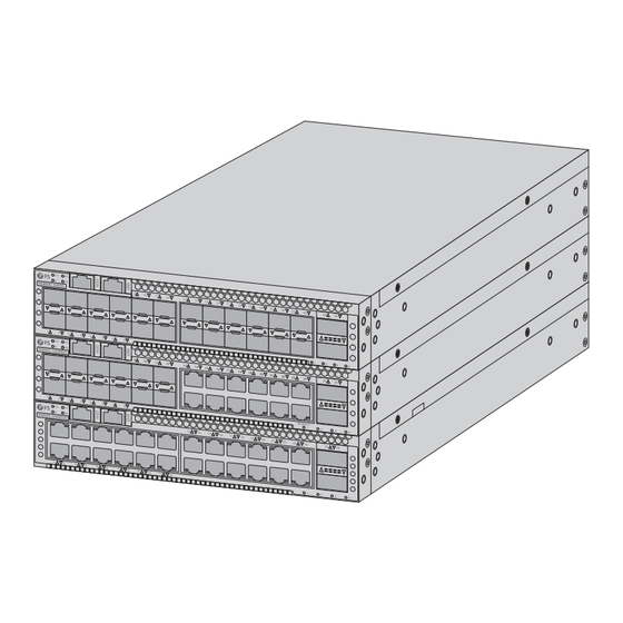
- Page 34 Einreihige Stapelung 1. Bringen Sie die hinteren Stapelhalterungen an den beiden Seiten der Switches mit den mitgelieferten Schrauben an. 2. Montieren Sie die vorderen Stapelhalterungen mit den Schrauben an den beiden Seiten der Switches.
- Page 35 Doppelreihige Stapelung 1. Befestigen Sie die mittleren Halterungen und verbinden Sie zwei Switches mit Schrauben als Rackbefestigung. 2. Montieren Sie die vorderen und hinteren Stapelhalterungen mit den mitgelieferten Schrauben an den beiden Seiten der Switches. Erdung des Switches 1. Schließen Sie ein Ende des Erdungskabels an eine geeignete Erdung an, z. B. an das Rack, in dem der Switch montiert ist.
- Page 36 ACHTUNG: Die Erdungsverbindung darf nur dann entfernt werden, wenn alle Verbindungen getrennt wurden. Anschließen der RJ45-Ports 1. Schließen Sie ein Ethernet-Kabel an den RJ45-Port eines Netzwerkgeräts an. 2. Schließen Sie das andere Ende des Ethernet-Kabels an den RJ45-Port des Switches an. Anschließen der SFP+-Ports...
- Page 37 1. Verbinden Sie den kompatiblen SFP+-Transceiver mit dem SFP+-Port. 2. Schließen Sie ein Glasfaserkabel an den Glasfaser-Transceiver an. Schließen Sie dann das andere Ende des Kabels an ein anderes Glasfasergerät an. WARNUNG: Laserstrahlen können zu Augenschäden führen. Schauen Sie nicht ohne Augenschutz in die Bohrungen von Transceivern oder Glasfasern.
- Page 38 Anschließen des Console-Ports 1. Verbinden Sie den RJ45-Steckverbinder des Console-Kabels mit dem RJ45-Console-Port des Switches. 2. Verbinden Sie die DB9-Buchse des Console-Kabels mit dem seriellen Port des Computers. Anschließen des MGT-Ports 1. Schließen Sie ein Ende eines Standard-RJ45-Ethernetkabels an den MGT-Port des Switches an.
-
Page 39: Anschließen Der Stromversorgung
Anschließen der Stromversorgung 1. Stecken Sie das Netzkabel in den Netz-Port auf der Rückseite des Switches. 2. Schließen Sie das andere Ende des Netzkabels an eine AC-Stromquelle an. HINWEIS: Über das RPS-Netzkabel können zwei Switches miteinander verbunden werden, um die Stromredundanz zwischen den beiden Switches umzusetzen. - Page 40 Kon gurieren des Switches Kon gurieren des Switches über die webbasierte Schnittstelle Schritt 1: Schließen Sie einen Computer über ein Netzwerkkabel an den Ethernet-Port des Switches an. Schritt 2: Stellen Sie die IP-Adresse des Computers auf 192.168.1.x ein („x“ ist eine beliebige Zahl zwischen 2 und 254).
- Page 41 Kon gurieren des Switches über den Console-Port Schritt 1: Schließen Sie einen Computer über das Console-Kabel an den Console-Port des Switches an. Schritt 2: Starten Sie die Terminalsimulationssoftware, z. B. HyperTerminal, auf dem Computer. Schritt 3: Stellen Sie die Parameter von HyperTerminal ein: Baud Rate auf 115200, Data Bits auf 8, Parity auf None und Stop Bits auf 1.
-
Page 42: Fehlerbehebung
Fehlerbehebung Das Netzteil liefert keinen Strom Alle LEDs auf der Vorderseite des Switches, des Lüftermoduls und des Bedienfelds des Netzteils sind aus. Der Lüfter funktioniert nicht. Ziehen Sie zunächst das Netzkabel des Netzteils ab, und überprüfen Sie dann Folgendes: 1. ob die Kabelanschlüsse des Racks ordnungsgemäß sind. 2. - Page 43 Produktgarantie FS garantiert seinen Kunden, dass wir bei Schäden oder fehlerhaften Artikeln, die auf unsere Verarbeitung zurückzuführen sind, eine kostenlose Rückgabe innerhalb von 30 Tagen nach Erhalt der Ware anbieten. Dies gilt nicht für Sonderanfertigungen oder maßgeschneiderte Lösungen. Garantie: Für die Produkte gilt eine eingeschränkte Garantie von 5 Jahren auf Material- und Verarbeitungsfehler.
- Page 44 Introduction Nous vous remercions d'avoir choisi les switchs d'entreprise. Ce guide est conçu pour vous familiariser avec la con guration des switchs et décrit comment procéder à leur déploiement. S5850C-24S2C S5850C-12XMS2C S5850C-24XMG2C Accessoires Support de Montage Court x1 Support de Montage Long x1 Support Mural x2 Rail Coulissant x1 Support de Montage Arrière x1...
- Page 45 Support Central (b) x1 Câble de Mise à la Terre x1 Câble de Console x1 Vis M3 x4 Vis M4 x16 Câble d'Alimentation x1 Câble d'Alimentation RPS x1 Support d'Empilage Avant x2 Support d'Empilage Arrière x2 Câble Réseau x1 Vis M6 x4 Écrou de Cage M6 x4 NOTE : Les accessoires peuvent varier par rapport à...
-
Page 46: Présentation Du Matériel
Présentation du Matériel Ports du Panneau Frontal S5850C-24S2C Console MGT SFP+ QSFP28 S5850C-12XMS2C Console MGT SFP+ RJ45 QSFP28 S5850C-24XMG2C Console MGT RJ45 QSFP28 Ports Description RJ45 Ports RJ45 100M/1G/2,5G/5G/10G pour connexion Ethernet SFP+ Ports SFP+ pour connexion 10G QSFP28 Ports QSFP28 pour connexion 100G Console Port console RJ45 pour la gestion en série Port Ethernet... - Page 47 LED du Panneau Frontal S5850C-24S2C Port 25-26 Port 1-24 Breakout S5850C-12XMS2C Port 1-24 Port 25-26 Port 1-24 Breakout S5850C-24XMG2C Port 1-24 Port 25-26 Port 1-24 Breakout...
- Page 48 LEDs État Description Vert Le système fonctionne normalement. Une alarme ou une erreur est détectée dans le Jaune système. Le système n'est pas allumé ou fonctionne Éteint anormalement. Bleu La fonction d'indication d'ID est activée. La fonction d'indication d'ID est désactivée. Éteint Vert Le port est relié...
-
Page 49: Conditions D'installation
Conditions d'Installation Avant de commencer l'installation, assurez-vous que vous disposez des éléments suivants : Un tournevis Phillips. Rack standard de 19 de large avec une hauteur minimale de 1U disponible. Câbles Ethernet RJ45 de catégorie 5e ou supérieure pour connecter les périphériques réseau. - Page 50 Installation du Switch Installation en Rack d'un Seul Switch 1. Fixez le rail coulissant au rack à l'aide des vis fournies. 2. Fixer le support de montage arrière sur un côté du switch à l'aide de deux vis, et assembler le support de montage arrière et le rail coulissant.
- Page 51 3. Fixez le kit de support de montage avant (court et long) sur les deux côtés du switch à l'aide des vis fournies. 4. Fixez le switch au rack à l'aide des vis M6 et des écrous à cage. Installation en Rack Deux-en-un 1.
- Page 52 3. Rassembler deux switchs et xer les kits de montage intermédiaires réunis à l'aide de quatre vis. 4. Fixez les deux supports de montage courts aux deux côtés des interrupteurs à l'aide de huit vis.
- Page 53 5. Fixez les switchs au rack à l'aide de vis M6 et d'écrous à cage. 6. Fixer le kit de support de montage arrière selon les besoins.
-
Page 54: Montage Mural
Montage Mural 1. Fixer les supports de montage sur les deux côtés du switch à l'aide des vis fournies. 2. Utilisez les vis d'expansion pour xer solidement le switch au mur. - Page 55 Empilage sur une Rangée 1. Installez les supports d'empilage arrière sur les deux côtés des switchs à l'aide des vis fournies. 2. Installez les supports d'empilage avant sur les deux côtés des switchs à l'aide des vis.
- Page 56 Empilage à Deux Rangs 1. Fixez les kits de montage du milieu et combinez deux switchs à l'aide de vis comme pour le montage en rack. 2. Installez les supports d'empilage avant et arrière sur les deux côtés des switchs à l'aide des vis fournies.
- Page 57 ATTENTION : La connexion à la terre ne peut être retirée avant que toutes les connexions ne soient déconnectées. Connexion des Port RJ45 1. Connectez un câble Ethernet au port RJ45 d'un périphérique réseau. 2. Connectez l'autre extrémité du câble Ethernet au port RJ45 du switch. Connexion des Ports SFP+...
- Page 58 1. Branchez l'émetteur-récepteur SFP+ compatible au port SFP+. 2. Connectez un câble à bre optique à l'émetteur-récepteur à bre optique. Connectez ensuite l'autre extrémité du câble à un autre dispositif à bre optique. AVERTISSEMENT : Les faisceaux laser peuvent provoquer des lésions oculaires. Ne pas regarder dans les alésages des émetteurs-récepteurs ou des bres optiques sans protection oculaire.
- Page 59 Connexion du Port Console 1. Insérez le connecteur RJ45 du câble de console au port de console RJ45 du switch. 2. Branchez le connecteur femelle DB9 du câble de console au port série de l'ordinateur. Connexion du Port MGT 1. Connectez une extrémité d'un câble Ethernet RJ45 standard au port MGT du switch. 2.
-
Page 60: Branchement De L'alimentation
Branchement de l'Alimentation 1. Branchez le câble d'alimentation CA dans le port d'alimentation situé sur le panneau arrière du switch. 2. Branchez l'autre extrémité du câble d'alimentation à une source d'alimentation CA. REMARQUE : Le câble d'alimentation RPS peut connecter deux switchs et e ectuer la redondance de l'alimentation entre les deux switchs. - Page 61 Con guration du Switch Con guration du Switch à l'Aide de l'Interface Web Étape 1 : Connectez un ordinateur au port Ethernet du switch à l'aide du câble réseau. Étape 2 : Réglez l'adresse IP de l'ordinateur sur 192.168.1.x ( x est un nombre quelconque compris entre 2 et 254).
- Page 62 Con guration du Switch à l'Aide du Port de Console Étape 1 : Connectez un ordinateur au port de console du switch à l'aide du câble de console. Étape 2 : Lancez le logiciel HyperTerminal sur l'ordinateur. Étape 3 : Dé nissez les paramètres de l'HyperTerminal : 115200 pour le Baud rate, 8 pour les Data bits, None pour la Parity et 1 pour les Stop bits.
-
Page 63: Dépannage
Dépannage Le Module d'Alimentation ne Fournit pas de Courant Tous les voyants du panneau frontal du switch, du module de ventilation et du panneau du module d'alimentation sont éteints. Le ventilateur ne fonctionne pas. Débranchez d'abord le câble d'alimentation du module d'alimentation, puis véri ez les aspects suivants : 1. -
Page 64: Garantie Du Produit
Garantie du Produit FS garantit à ses clients que tout article endommagé ou défectueux en raison de sa fabrication pourra être retourné gratuitement dans un délai de 30 jours à compter de la date de réception de la marchandise. Cette garantie ne s'applique pas aux articles fabriqués sur mesure ou aux solutions personnalisées. - Page 65 イントロダクション このたびは、企業向けスイッチをお買いあげいただき、誠にありがとうございます。本ガ イドは、スイッチの概要とネットワークへの導入方法について説明します。 S����C-��S�C S����C-��XMS�C S����C-��XMG�C アクセサリー ショート取付けブラケット x� ロング取付けブラケット x� 壁取付けブラケット x� スライドレール x� リア取付けブラケット x� ミドルマウント(a) x�...
- Page 66 ミドルマウント(b) x� アースケーブル x� コンソールケーブル x� M�ネジ x� M�ネジ x�� 電源コード x� RPS電源コード x� フロントスタッキ リアスタッキ ングブラケット x� ングブラケット x� ネットワークケーブル x� M�ケージナット x� M�ネジ x� 注:アクセサリーの図は参考用です。 注: この電源コードは他の機器には使用できません。また、他の電源コードはこ の機器に使用しないでください。...
- Page 67 ハードウェアの概要 フロントパネルのポート S����C-��S�C ConsoleMGT SFP+ QSFP�� S����C-��XMS�C Console MGT SFP+ RJ�� QSFP�� S����C-��XMG�C Console MGT RJ�� QSFP�� ポート 説明 イーサネット接続用���M/�G/�.�G/�G/��G RJ��ポート RJ�� SFP+ ��G接続用SFP+ポート QSFP�� ���G接続用QSFP��ポート Console シリアル管理用RJ��コンソールポート イーサネット管理ポート...
- Page 68 フロントパネルのLED S����C-��S�C Port ��-�� Port �-�� Breakout S����C-��XMS�C Port �-�� Port ��-�� Port �-�� Breakout S����C-��XMG�C Port �-�� Port ��-�� Port �-�� Breakout...
- Page 69 状態 説明 点灯(緑) システムは正常です。 システムにアラームまたはその他のエラーが発生し 点灯(黄) ています。 システムの電源が入っていないか、異常に動作して 消灯 います。 点灯(青) ID表示機能が有効になっています。 消灯 ID表示機能が無効になっています。 点灯(緑) ポートは����Mでリンクされています。 点滅(緑) ����Mパケットを送受信しています。 点灯(橙) ポートは���Mでリンクされています。 点滅(橙) ���Mパケットを送受信しています。 ポートが��Mでリンクされているか、リンクされて 消灯 いません。 �台のデバイスを同時に使用する場合、冗長電源は接 点灯(黄) 続されていません。 �台のデバイスを同時に使用する場合、冗長電源は接 消灯 続されています。 点灯(緑) ポートは��Gでリンクされています。 点滅(緑) ��Gパケットを送受信しています。 ポート�-�� 点灯(黄) ポートは���M/�G/�.�G/�Gでリンクされています。 点滅(黄) ���M/�G/�.�G/�Gのパケットを送受信しています。 消灯...
- Page 70 設置要件 設置前に、以下の条件が整っていることを確認してください。 プラスドライバー 高さ�U以上の標準サイズ��インチ幅ラック ネットワーク機器接続用カテゴリー�eまたはその以上のRJ��イーサネットケーブル 環境要件 設置場所の温度が�°C~��°Cに保たれていることを確認してください。 設置場所の相対湿度が��%~��%に保たれていることを確認してください。 設置場所に水漏れ、水滴、結露、湿気がないことを確認してください。 設置場所にほこりがないようにしてください。 設置場所は換気の良い場所にしてください。スイッチの周囲に十分な空気の流れがあ ることを確認してください。 危険な状況を避けるために、スイッチが水平で安定していることを確認してください。 ラックと作業台が適切に接地されていることを確認してください。...
- Page 71 スイッチの取り付け シングルスイッチのラックマウント �. 付属のネジでスライドレールをラックに固定します。 �. リア取付けブラケットを�本のネジでスイッチの片側に固定し、リア取付けブラケットと スライドレールを組み立てます。...
- Page 72 �. 付属のネジでフロント取付けブラケットキット(ショートとロング)をスイッチの両側 に固定します。 �. M�ネジとケージナットでスイッチをラックに固定します。 � in �Uラックマウント �. �つのミドルマウント(a)を�本のネジで�つのスイッチに固定します。 �. �つのミドルマウント(b)を�本のネジでもう一方のスイッチに固定します。...
- Page 73 �. �つのスイッチを組み合わせ、組み合わせたミドルマウントキットを�本のネジで固定し ます。 �. �つのショート取付けブラケットを�本のネジでスイッチの両側に固定します。...
- Page 74 �. M�ネジとケージナットでスイッチをラックに固定します。 �. 必要に応じて、リア取付けブラケットキットを固定します。...
- Page 75 ウォールマウント �. 付属のネジで取付けブラケットをスイッチの両側に固定します。 �. 拡張ネジを使用して、スイッチを壁にしっかりと固定します。...
- Page 76 一列スタッキング �. 付属のネジを使用して、リアスタッキングブラケットをスイッチの両側に取り付けます。 �. ネジでフロントスタッキングブラケットをスイッチの両側に取り付けます。...
- Page 77 二列スタッキング �. ミドルマウントキットを固定し、ラックマウントとして�台のスイッチをネジで組み合わ せます。 �. フロントとリアのスタッキングブラケットを付属のネジでスイッチの両側に取り付けま す。 スイッチの接地 �. アースケーブルの一端を、スイッチが取付けられているラックなどの適切な接地点に接 続します。 �. アースラグを、ネジとワッシャーでスイッチのバックパネルの接地点に固定します。...
- Page 78 注意:すべての電源接続が切断されていない限り、アース接続を取り外さないで ください。 RJ��ポートの接続 �. イーサネットケーブルをネットワーク機器のRJ��ポートに接続します。 �. イーサネットケーブルのもう一方の端をスイッチのRJ��ポートに接続します。 SFP+ポートの接続...
- Page 79 �. 互換性のあるSFP+トランシーバをSFP+ポートに接続します。 �. 光ファイバケーブルをファイバトランシーバに接続します。次に、ケーブルのもう一方 の端を別のファイバデバイスに接続します。 警告:レーザー光線は目に損傷を与える可能性があります。保護メガネを着用せ ずに、光トランシーバや光ファイバの穴を覗き込まないでください。 QSFP��ポートの接続 �. 互換性のあるQSFP��トランシーバをQSFP��ポートに接続します。 �. 光ファイバケーブルをファイバトランシーバに接続します。次に、ケーブルのもう一方 の端を別のファイバデバイスに接続します。...
- Page 80 コンソールポートの接続 �. コンソールケーブルのRJ��コネクタをスイッチのRJ��コンソールポートに挿入します。 �. コンソールケーブルのDB�メスコネクタをコンピュータのシリアルポートに接続します。 MGTポートの接続 �. 標準RJ��イーサネットケーブルの一端をMGTポートに接続します。 �. ケーブルのもう一方の端をコンピュータに接続します。...
- Page 81 電源の接続 �. AC電源コードをスイッチのバックパネルにある電源ポートに差し込みます。 �. 電源コードのもう一方の端をAC電源に接続します。 注:RPS電源コードは、�つのスイッチを接続し、�つのスイッチ間の電源冗長性 を実現できます。さらに、スイッチAの電源が故障した場合、もう�つのスイッチ Bからの電源がスイッチAとスイッチB自体に同時に電力を供給できます。 警告:電源が入っている間は、電源コードを取り付けないでください。...
- Page 82 スイッチの設定 ウェブベースインターフェースからの設定 Step �:ネットワークケーブルを使用してコンピュータをスイッチのイーサネットポート に接続します。 Step �:コンピュータのIPアドレスを「���.���.�.x」( [x」は�~���の任意の数字)に 設定します。 Step �:ブラウザを開き、「http://���.���.�.�」と入力し、デフォルトのユーザー名 「admin」とパスワード「admin」を入力します。 Step �:「Login」をクリックすると、ウェブベースの設定ページが表示されます。...
- Page 83 コンソールポートからの設定 Step �:コンソールケーブルを使用して、コンピュータとスイッチのコンソールポートを 接続します。 Step �:コンピュータ上でHyperTerminalなどの端末シミュレーションソフトウェアを起 動します。 Step �:HyperTerminalのパラメータを設定します:ボーレート(Baud rate)を������、 データビット(Data bits)を�、パリティ(Parity)をなし(None)、ストップビット (Stop bits)を�に設定します。 Quick Connect Protocol: Serial The port may be manually entered or selected from the list. Port: COM5 USB Serial Port 115200 Baud rate: Flow Control DTR/DSR Data bits: RTS/CTS Parity:...
- Page 84 トラブルシューティング 電源モジュールが電力を供給できない スイッチのフロントパネル、ファンモジュール、および電源モジュールのパネルのLEDが すべて消灯しています。ファンが動作しません。まず、電源モジュールの電源コードを外 し、以下を確認してください: �. ラックのケーブル接続が正しいか。 �. 電源ソケットと電源コードの接続が緩んでいないか。 �. 電源モジュールと電源コードの接続が緩んでいないか。 �. 電源モジュールが所定の位置に挿入されているか。 スイッチのリモート接続に失敗した場合 �. pingでネットワーク接続をテストします。 �. ネットワークに到達可能な場合は、スイッチを再起動してください。 �. 対応するサービスが有効になっているか確認してください。 光ポートがリンクアップできない �. 光ファイバケーブルの受信側と送信側が正しく接続されているか確認してください。 �. 相互接続のトランシーバの波長が同じか確認してください。 �. 相互接続の距離がトランシーバでマークされた距離内であるかどうかを確認します。 �. 相互接続のレートが同じであるか、または異なるレートをサポートするポートのレート モードが正しく設定されているか確認してください。 �. 光ファイバのタイプが要件を満たしているか確認してください。 端末デバイスの画面に文字が表示されない/文字が歪んでいる �. コンソールケーブルが正しく接続されているか確認してください。 �. コンソールケーブルが破損していないか確認してください。 �. スイッチのコンソールポートと端末デバイスのポートが一致しているか確認してくださ い。 �.
- Page 85 製品保証 FSは、カスタム製品又はカスタムソリューションを除き、当社の過失による製品の破損や 不良品があった場合、お客様が製品を受け取った日から��日以内に無料で返品、交換をす ることを保証します。 保証:この製品は、材料または製造上の欠陥に対して�年間の限定保証を提供し ます。保証の詳細については、下記のURLをご参照ください。 https://www.fs.com/jp/policies/warranty.html 返品:返品を希望される場合、方法については下記のURLをご参照ください。 https://www.fs.com/jp/policies/day_return_policy.html オンラインリソース その他の技術資料については、下記のURLをご参照ください。 https://www.fs.com/jp/technical_documents.html FSアプリをダウンロード QRコードを読み取り、App StoreまたはGoogle PlayストアからFSア プリをダウンロードしてインストールできます。若しくは下記のURL にアクセスしてください。 https://www.fs.com/jp/appdownload.html...
-
Page 86: Compliance Information
Compliance Information Any Changes or modi cations not expressly approved by the party responsible for compliance could void the user's authority to operate the equipment. Note: This equipment has been tested and found to comply with the limits for a Class A digital device, pursuant to part 15 of the FCC Rules. - Page 87 2014/35/EU, 2011/65/EU und (EU)2015/863 . Eine Kopie der EU-Konformitätserklärung nden Sie unter www.fs.com/de/company/quality_control.html. FS.COM GmbH déclare par la présente que ce dispositif est conforme à la Directive 2014/30/EU, 2014/35/EU, 2011/65/EU et (EU)2015/863 . Une copie de la Déclaration de Conformité de l'UE est disponible à l'adresse suivante https://www.fs.com/fr/company/quality_control.html.
- Page 88 Do not dispose of WEEE as unsorted municipal wasteand have to collect such WEEE separately. Q.C. PASSED Copyright © 2024 FS.COM All Rights Reserved.
Need help?
Do you have a question about the S5850C Series and is the answer not in the manual?
Questions and answers