FS S5860 Series Quick Start Manual
Managed l3 enterprise switches
Hide thumbs
Also See for S5860 Series:
- Hardware installation and maintenance manual (32 pages) ,
- Quick start manual (70 pages)
Table of Contents
Advertisement
MG MT
STAT US PWR1
PWR2 FAN
MGM T ID
FUN C
CON SOL E
1F
2F
3F
4F
5F
6F
7F
8F
9F
10F
11F
Sta tus
ID
S58 60- 48S
C
SYS
PWR
FAN
PoE
MGM T
1
PoE
FUN C
CON SOL E
Gre en= 10G
S5860 Series Switches
MANAGED L3 ENTERPRISE SWITCHES
Quick Start Guide
1
2
3
4
5
6
7
8
9
10
11
12
13
14
15
16
17
18
19
12F
13F
14F
15F
16F
17F
18F
19F
20F
21F
22F
23F
24F
25F
26F
27F
28F
29F
30F
31F
2
3
4
5
6
7
8
9
10
11
12
13
14
15
16
17
18
19
20
21
/5G /2.5 G/1
G
Yell ow= 100
M
On= Link Flas
hing =AC T
PoE LED Mod
e:Gr een =Go
od Sup ply
Yell ow= Ove
r Loa d
V1.0
20
21
22
1
23
2
24
3
4
40G Brea kou
t
25
26
25G
40G
32F
33F
34F
35F
36F
37F
38F
39F
40F
41F
42F
43F
44F
45F
46F
47F
48F
49F
50F
51F
22
23
24
25
26
27
28
29
30
31
32
S58 60- 20S Q
52F
53F
54F
55F
56F
100 G
S5 86 0-2 4X
B-U
Advertisement
Table of Contents

Subscribe to Our Youtube Channel
Related Manuals for FS S5860 Series


Summary of Contents for FS S5860 Series
- Page 1 /5G /2.5 G/1 Yell ow= 100 On= Link Flas S5 86 0-2 4X hing =AC T PoE LED Mod e:Gr een =Go od Sup ply Yell ow= Ove r Loa d S5860 Series Switches MANAGED L3 ENTERPRISE SWITCHES Quick Start Guide V1.0...
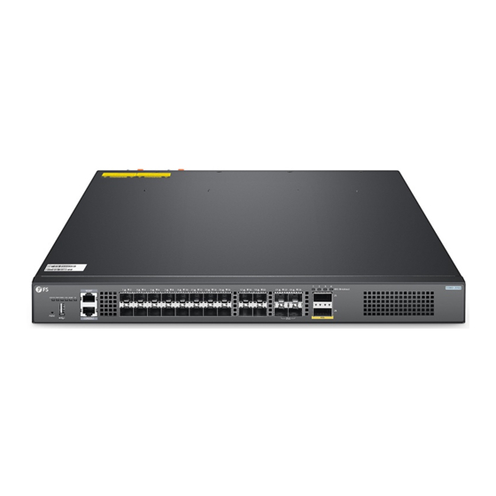
- Page 2 Introduction Thank you for choosing S5860 Series Switches. This guide is designed to familiarize you with the layout of the switch and describes how to deploy the switch in your network. S5860-20SQ 40G Breakout MGMT STATUS PWR1PWR2 FAN MGMT ID...
-
Page 3: Hardware Overview
M6 Screw x8 M6 Nut x8 Slide Rail x2 Inner Rail x2 NOTE: S5860 series switches have dust plugs delivered with them. Keep the dust plugs properly and use them to protect idle optical ports. Hardware Overview Front/Back Panel Ports S5860-20SQ... - Page 4 S5860-48SC SFP+ QSFP28 100G Status S5860-48SC MGMT AFM-S48SC-FB AFM-S48SC-FB AFM-S48SC-FB AFM-S48SC-FB MGMT Link PWR2 PWR1 Status Status Status Status Status FUNC CONSOLE CONSOLE S5860-24XB-U MGMT S5860-24XB-U MGMT FUNC CONSOLE Green=10G/5G/2.5G/1G Yellow=100M On=Link Flashing=ACT PoE LED Mode:Green=Good Supply Yellow=Over Load USB CONSOLE RJ45 SFP+ SFP28 Ports...
- Page 5 Front/Back Panel Buttons Ports Description S5860-20SQ S5860-20SQ 40G Breakout MGMT STATUS PWR1PWR2 FAN MGMT ID FUNC CONSOLE FUNC S5860-48SC AFM-S48SC-FB AFM-S48SC-FB AFM-S48SC-FB AFM-S48SC-FB MGMT Link PWR2 PWR1 Status Status Status Status Status FUNC CONSOLE FUNC S5860-24XB-U S5860-24XB-U MGMT FUNC CONSOLE Green=10G/5G/2.5G/1G Yellow=100M On=Link Flashing=ACT...
- Page 6 Back Panel S5860-20SQ M1SFANI-F M1SFANI-F Status Status FAN1 FAN2 PWR1 Grounding Point Fan Slots Dual Power Supplies S5860-48SC Fan Slots Grounding Point AFM-S48SC-FB AFM-S48SC-FB AFM-S48SC-FB AFM-S48SC-FB MGMT Link PWR2 PWR1 Status Status Status Status Status FUNC CONSOLE Dual Power Supplies S5860-24XB-U M1SFANI-F M1SFANI-F...
- Page 7 LEDs Status Description Solid Green The system works properly. STATUS Solid Yellow The temperature reaches the threshold value. The power module is NOT in the position. Solid Green The power module works properly. PWR1/PWR2 Solid Red A power fault occurs. Solid Green The fan works properly.
- Page 8 S5860-48SC SFP+ QSFP28 100G Status S5860-48SC STATUS ID ID MGMT AFM-S48SC-FB AFM-S48SC-FB AFM-S48SC-FB AFM-S48SC-FB MGMT Link PWR2 PWR1 Status Status Status Status Status FUNC CONSOLE STATUS LEDs Status Description The system is powered o . 1. One of the modules of the system fails. 2.
- Page 9 LEDs Status Description The SFP+ port is NOT connected. Solid Green The SFP+ port is connected at 1/10G. SFP+ Blinking Green The SFP+ port is transmitting or receiving data at 1/10G. The QSFP28 port is NOT connected. Solid Green The QSFP28 port is connected at 40/100G. QSFP28 Blinking Green The QSFP28 port is transmitting or receiving data at 40/100G.
- Page 10 LEDs Status Description The power module is NOT in the position. Solid Green The power module works properly. 1. A power fault occurs. Solid Red 2. No AC power cable is plugged in. 3. The power model does not match. Solid Green The fan works properly.
- Page 11 LEDs Status Description The SFP+ port is NOT connected. Solid Green The SFP+ port is connected at 1/10G. SFP+ Blinking Green The SFP+ port is transmitting or receiving data at 1/10G. The SFP28 port is NOT connected. Solid Green The SFP28 port is connected at 10/25G. SFP28 Blinking Green The SFP28 port is transmitting or receiving data at 10/25G.
-
Page 12: Installation Requirements
Installation Requirements Before you begin the installation, make sure that you have the followings: Phillips screwdriver. Standard-sized, 19" wide rack with a minimum of 1U height available. Category 5e or higher RJ-45 Ethernet cables, ber optical cables and console cable for connecting network devices. -
Page 13: Mounting The Switch
Mounting the Switch Desk Mounting 1. Attach four rubber pads to the bottom. 2. Place the chassis on a desk. Rack Mounting 40 G Bre ak ou t 1. Secure the mounting brackets to the two sides of the switch with supplied M4 screws. -
Page 14: Installing The Power Supply Module
2. Attach the switch to the rack using four M6 screws and cage nuts. Installing the Power Supply Module M 1 S FA N I- M 1 S FA N I- St at us St at us FA N 2 PW R1 1. -
Page 15: Grounding The Switch
Grounding the Switch M 1 SF A N I- M 1 SF A N I- FA N 1 St at us 1. Connect one end of the grounding cable to a proper earth ground, such as the rack in which the switch is mounted. - Page 16 Connecting the RJ45 Ports 1. Connect an Ethernet cable to the RJ45 port of IP cameras, IP telephone, Access Points (AP), or other network devices. 2. Connect the other end of the Ethernet cable to the RJ45 port of the switch. Connecting the SFP/SFP+ Ports M GM T STA TU S PW...
- Page 17 Connecting the SFP28 Ports 1. Plug the compatible SFP28 transceiver into the SFP28 port. 2. Connect a ber optic cable to the ber transceivers. Then connect the other end of the cable to another ber device. Connecting the QSFP+ Ports S5 86 0- 20 1.
-
Page 18: Connecting The Console Port
Connecting the QSFP28 Ports 10 F 11 F 12 F 13 F 14 F 15 F 16 F 17 F 18 F 19 F 20 F 21 F 22 F 23 F 24 F 25 F 26 F 27 F 28 F 29 F 30 F... -
Page 19: Stacking The Switches
S5 86 0- 20 40 G The S5860 series switches support stacking up to 2 switches between the same models together. The switch can be physically stacked using optical ber cables connected to SFP+/SFP28 transceivers or 10/25G Direct Attach Cables (DAC). Any two SFP+/SFP28 ports on the switch can be used for physical stacking. - Page 20 Con guring the Switch Con guring the Switch Using the Web-based Interface Step 1: Connect the computer to the Management port of the switch using the network cable. Step 2: Set the IP address of the computer to 192.168.1.x. (“x” is any number from 2 to 254.) I nter net Protocol Ver sion 4 ( TCP / IP v 4) Prope r tie s General Yo u c a n g e t I P s e t t i n g s a s s i g n e d a u t o m a t i c a l l y i f y o u r n e t w o r k...
- Page 21 Con guring the Switch Using the Console Port Step 1: Connect a computer to the switch's console port using the console cable. Step 2: Start the terminal simulation software such as HyperTerminal on the computer. Step 3: Set the parameters of the HyperTerminal: 9600 bits per second, 8 data bits, no parity, 1 stop bit and no ow control.
-
Page 22: Troubleshooting
Troubleshooting Power System Fault The indicator on the front panel of host is OFF. The Status indicator of fan module is OFF, and the fan does not work. The indicator on the panel of the power module is OFF and the fan does not work. Please check the following: First disconnect the power cord of the power module. -
Page 23: Support And Other Resources
Product Warranty FS ensures our customers that any damage or faulty items due to our workmanship, we will o er a free return within 30 Days from the day you receive your goods. This excludes any custom made items or tailored solutions.
Need help?
Do you have a question about the S5860 Series and is the answer not in the manual?
Questions and answers