FS S5810 Series Quick Start Manual
Managed l2/l3 enterprise switches
Hide thumbs
Also See for S5810 Series:
- Quick start manual (66 pages) ,
- Hardware installation and maintenance manual (28 pages) ,
- Quick start manual (53 pages)
Table of Contents
Advertisement
CON SOL E
STATU S PWR1
1
PWR2 MGMT
2
3
4
5
6
MINI CON SOLE
MGM T
On= Link Flas
hing =AC T
Gree n=1 000
CON SOL E
1
STATU S PWR1
2
PWR2 MGMT
3
4
5
6
MINI CON SOLE
MGM T
On= Link Flas
hing =AC T
Gree n=1 000
M Yello w=1
CON SOL E
STATU SPWR
1
1 PWR2 MGMT
2
3
PoE
4
5
6
PoE
MINI CON SOLE
MGM T
On= Link Flas
hing =AC T
Gree n=1 000
M Yello w=1
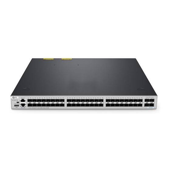
S5810 Series Switches
MANAGED L2/L3 ENTERPRISE SWITCHES
Quick Start Guide
CO MB O
7
8
1
2
3
4
5
6
7
8
9
10
11
12
13
14
15
16
17
18
M Yell ow=
10/1 00M
7
8
9
10
11
12
13
14
15
16
17
18
19
20
21
22
23
24
25
26
27
00M
7
8
9
10
11
12
13
14
15
16
17
18
19
20
21
22
23
24
25
26
27
0/10 0M
V1.0
19
20
21
22
23
24
25
26
SFP +
27
28
29
30
31
32
28
29
30
31
32
33
34
35
36
37
38
39
40
41
42
43
44
45
46
47
48
28
29
30
31
32
33
34
35
36
37
38
39
40
41
42
43
44
45
46
47
48
S58 10- 28F S
SFP +
49
50
51
52
S58 10- 48F S
SFP +
49
50
51
52
S58 10- 48T S-P
PoE +
Advertisement
Table of Contents

Related Manuals for FS S5810 Series


Summary of Contents for FS S5810 Series
- Page 1 MINI CON SOLE S58 10- 48F S MGM T On= Link Flas hing =AC T Gree n=1 000 SFP + M Yello w=1 0/10 0M S58 10- 48T S-P PoE + S5810 Series Switches MANAGED L2/L3 ENTERPRISE SWITCHES Quick Start Guide V1.0...
- Page 2 Introduction Thank you for choosing S5810 Series Switches. This guide is designed to familiarize you with the layout of the switch and describes how to deploy the switch in your network. COMBO SFP+ S5810-28FS CONSOLE STATUS PWR1 PWR2 MGMT S5810-28FS...
-
Page 3: Hardware Overview
Hardware Overview Front Panel Ports S5810-28FS MINI CONSOLE CONSOLE COMBO SFP+ S5810-28FS CONSOLE STATUS PWR1 PWR2 MGMT MINI CONSOLE MGMT On=Link Flashing=ACT Green=1000M Yellow=10/100M USB MGMT COMBO SFP+ S5810-48FS MINI CONSOLE CONSOLE SFP+ CONSOLE STATUS PWR1 PWR2 MGMT MINI CONSOLE MGMT S5810-48FS On=Link Flashing=ACT Green=1000M Yellow=100M... -
Page 4: Front Panel Button
Ports Description An RJ45 console port for serial management CONSOLE A USB management port for software and con guration backup and o ine software upgrade Front Panel Button S5810-48TS-P SFP+ CONSOLE STATUSPWR1 PWR2 MGMT MINI CONSOLE MGMT S5810-48TS-P PoE+ On=Link Flashing=ACT Green=1000M Yellow=10/100M Description Button Switch the display mode between PoE mode and switch mode. - Page 5 S5810-48TS-P Input Input Output Output PWR1 PWR2 Grounding Point Dual Power Supplies Front Panel LEDs S5810-28FS STATUS PWR2 COMBO SFP+ S5810-28FS CONSOLE STATUS PWR1 PWR2 MGMT MINI CONSOLE MGMT On=Link Flashing=ACT Green=1000M Yellow=10/100M PWR1 MGMT RJ45 SFP+ S5810-48FS STATUS PWR2 SFP+ CONSOLE STATUS PWR1 PWR2 MGMT...
- Page 6 LEDs Status Description The system is powered o . The switch is being initialized with 3Hz blinking. Blinking Green (3Hz) Continuous blinking indicates errors. Blinking Green (10Hz) Supports remote on/o to locate the switch. STATUS Solid Green The switch is operational. Temperature warning, check the working environment of Solid Yellow the switch immediately.
- Page 7 LEDs Status Description PoE is not enabled. Solid Green PoE is enabled. The port is operational. PoE (1-48) Solid Yellow The port has a PoE fault of overload. The port is not connected. Solid Green The port is connected at 1000 Mbps. Blinking Green The port is receiving or transmitting tra c at 1000 Mbps.
-
Page 8: Installation Requirements
Installation Requirements Before you begin the installation, make sure that you have the followings: Phillips screwdriver. Standard-sized, 19" wide rack with a minimum of 1U height available. Category 5e or higher RJ-45 Ethernet cables, ber optical cables and console cable for connecting network devices. -
Page 9: Mounting The Switch
1. Attach four rubber pads to the bottom. 2. Place the chassis on a desk. M od ul e1 Rack Mounting SF P + S5 81 0- 28 FS 1. Secure the mounting brackets to the two sides of the switch with eight M4 screws. -
Page 10: Installing The Power Supply Module
SF P+ S5 81 0- 28 2. Attach the switch to the rack using four M6 screws and cage nuts. Installing the Power Supply Module M od ul e2 PW R1 PW R1 PW R2 1. Take a new power module out of the package and con rm the input mode and the input parameters of the power module match the requirements. -
Page 11: Grounding The Switch
Grounding the Switch M od ul e1 M od ul e2 PW R1 1. Connect one end of the grounding cable to a proper earth ground, such as the rack in which the switch is mounted. 2. Secure the grounding lug to the grounding point on the switch back panel with the washers and screws. - Page 12 Connecting the RJ45 Ports PW R2 1. Connect an Ethernet cable to the RJ45 port of IP cameras, IP telephone, Access Points (AP), or other network devices. 2. Connect the other end of the Ethernet cable to the RJ45 port of the switch. Connecting the SFP/SFP+ Ports CO NS OL E STA TUS PW...
-
Page 13: Connecting The Console Port
Connecting the Console Port CO NS OL E STA TUS PW R1 PW R2 MG MT CO M BO MI NI CO NS OL E M GM T On =L in k Fla sh in g= AC T Gr ee n= 10 00 M Ye llo w= 10 /1 00 M... -
Page 14: Stacking The Switches
MGMT On=Link Flashing=ACT Green=1000M Yellow=10/100M The S5810 series switches support stacking up to 8 switches between the same series together. The switch can be physically stacked using optical ber cables connected to SFP/SFP+ transceivers or 1G/10G Direct Attach Cables (DAC). Only four SFP+ uplinks on the switch can be used for physical stacking. - Page 15 Con guring the Switch Con guring the Switch Using the Web-based Interface Step 1: Connect the computer to the Management port of the switch using the network cable. Step 2: Set the IP address of the computer to 192.168.1.x.(“x” is any number from 2 to 254.) I nter net Protocol Ver sion 4 ( TCP / IP v 4) Prope r tie s General Yo u c a n g e t I P s e t t i n g s a s s i g n e d a u t o m a t i c a l l y i f y o u r n e t w o r k...
- Page 16 Con guring the Switch Using the Console Port Step 1: Connect a computer to the switch's console port using the console cable. Step 2: Start the terminal simulation software such as HyperTerminal on the computer. Step 3: Set the parameters of the HyperTerminal: 9600 bits per second, 8 data bits, no parity, 1 stop bit and no ow control.
-
Page 17: Troubleshooting
Troubleshooting Power System Fault The indicator on the front panel of host is OFF. The Status indicator of fan module is OFF, and the fan does not work. The indicator on the panel of the power module is OFF and the fan does not work. Please check the following: First, disconnect the power cord of the power module. -
Page 18: Support And Other Resources
Product Warranty FS ensures our customers that any damage or faulty items due to our workmanship, we will o er a free return within 30 Days from the day you receive your goods. This excludes any custom made items or tailored solutions.
Need help?
Do you have a question about the S5810 Series and is the answer not in the manual?
Questions and answers