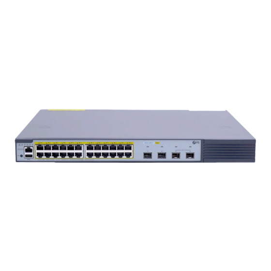
FS S3410-24TS-P Quick Start Manual
24-port gigabit l2+/l3 poe managed switches
Hide thumbs
Also See for S3410-24TS-P:
- Quick start manual (20 pages) ,
- Configuration manual (7 pages) ,
- Quick start manual (70 pages)

Related Manuals for FS S3410-24TS-P


Summary of Contents for FS S3410-24TS-P
- Page 1 S3410-24TS-P/S5860-24XB-U 24-PORT GIGABIT L2+/L3 POE MANAGED SWITCHES Quick Start Guide V1.1...
- Page 2 Introduction Thank you for choosing S3410-24TS-P & S5860-24XB-U POE Switches. This guide is designed to familiarize you with the layout of the switches and describes how to deploy the switches in your network. S3410-24TS-P PoE+ Status M1 M2 PWR1 PWR2 PoE...
-
Page 3: Hardware Overview
Hardware Overview Front Panel Ports S3410-24TS-P CONSOLE S3410-24TS-P PoE+ Status M1 M2 PWR1 PWR2 PoE CONSOLE SFP+ Green=1000M Yellow=10/100M On=Link Flashing=ACT PoE LED:Green=Good Supply Yellow=Over Load RJ45 RJ45/SFP Combo SFP+ Ports Description RJ45 10/100/1000BASE-T ports for Ethernet connection RJ45/SFP Combo... - Page 4 A USB management port for software and con guration backup and o ine software upgrade CONSOLE An RJ45 console port for serial management An out-of-band Ethernet management port MGMT Front Panel Buttons S3410-24TS-P S3410-24TS-P PoE+ Status M1 M2 PWR1 PWR2 PoE CONSOLE SFP+ Green=1000M Yellow=10/100M On=Link Flashing=ACT...
-
Page 5: Back Panels
Back Panels S3410-24TS-P Module1 Module2 Input Input Power Output Output Expansion Module Slot Dual Power Supplies Grounding Point S5860-24XB-U M1SFANI-F M1SFANI-F M1SFANI-F FAN1 FAN2 FAN3 PWR1 PWR2 Input Input Output Output Status Status Status Grounding Point Fan Slot Dual Power Supplies... -
Page 6: Status Description
LEDs Status Description There is no expansion module or the expansion module is not correctly installed. M1/M2 Solid Green The expansion module is correctly installed. The power module is not in place. The power module is in place but the AC power cord or PWR1/PWR2 Solid Red switch is abnormal. - Page 7 S5860-24XB-U RJ45 SFP28 S5860-24XB-U MGMT FUNC CONSOLE Green=10G/5G/2.5G/1G Yellow=100M On=Link Flashing=ACT PoE LED Mode:Green=Good Supply Yellow=Over Load MGMT PoE (1-24) SFP+ LEDs Status Description The system is powered o . 1. A system fault occurs. Solid Red 2. The temperature reaches the upper limit. Blinking Green Initialization is in progress.
-
Page 8: Installation Requirements
LEDs Status Description The RJ45 port is NOT connected. Solid Green The RJ45 port is connected at 1G/2.5G/5G/10G. The RJ45 port is transmitting or receiving data at RJ45 Blinking Green 1G/2.5G/5G/10G. Yellow The RJ45 port is connected at 100Mbps. Blinking Yellow The RJ45 port is transmitting or receiving data at 100Mbps. -
Page 9: Site Environment
Site Environment: Do not operate it in an area that exceeds an ambient temperature of 50°C. Standard-sized, 19" wide rack with a minimum of 1U height available. Be sure that the switch is level and stable to avoid any hazardous conditions. Do not install the equipment in a dusty environment. -
Page 10: Rack Mounting
Rack Mounting 1. Secure the mounting brackets to the two sides of the S3410-24TS-P switch with eight M4 screws. (S5860-24XB-U switch with six M4 screws by default, another 2 screws for redundant.) 2. Attach the switch to the rack using four M6 screws and cage nuts. -
Page 11: Wall Mounting
Wall Mounting 1. Secure the mounting brackets to the two sides of the switch with supplied screws. 2. Use the expansion screws to securely attach the mounting brackets on the wall. -
Page 12: Installing The Power Supply Module
Installing the Power Supply Module 1. Take a new power module out of the package and con rm the input mode and the input parameters of the power module match the requirements. 2. Remove the blank panel and take the plane printed with power information as the top panel of the power module. -
Page 13: Grounding The Switch
Grounding the Switch 1. Connect one end of the grounding cable to a proper earth ground, such as the rack in which the switch is mounted. 2. Secure the grounding lug to the grounding point on the switch back panel with the washers and screws. -
Page 14: Connecting The Power
Connecting the Power 1. Plug the AC power cord into the power port on the back of the switch. 2. Connect the other end of the power cord to an AC power source. WARNING: Do not install power cable while the power is on. Connecting the RJ45 Ports 1. - Page 15 Connecting the SFP/SFP+ Ports 1. Plug the compatible SFP/SFP+ transceiver into the SFP/SFP+ port. 2. Connect a ber optic cable to the ber transceiver. Then connect the other end of the cable to another ber device. WARNING: Laser beams will cause eye damage. Do not look into bores of optical modules or optical bers without eye protection.
-
Page 16: Connecting The Console Port
Connecting the Console Port 1. Insert the RJ45 connector into the RJ45 console port on the front of the switch. 2. Connect the DB9 female connector of the console cable to the serial port on the computer. Connecting the MGMT Port 1. -
Page 17: Stacking The Switches
Stacking the Switches Stacking the S3410-24TS-P Switch The S3410-24TS-P switch supports stacking up to 4 switches between the same models together. The switch can be physically stacked using optical ber cables connected to SFP+ transceivers or 10G Direct Attach Cables (DAC). The two SFP+ ports on the switch can be used for physical stacking. - Page 18 Con guring the Switch Con guring the Switch Using the Web-based Interface Step 1: Connect the computer to any Ethernet port of the S3410-24TS-P switch using the network cable, and connect the computer to the Management port of the S5860-24XB-U switch using the network cable.
-
Page 19: Troubleshooting
Con guring the Switch Using the Console Port Step 1: Connect a computer to the switch's console port using the console cable. Step 2: Start the terminal simulation software such as HyperTerminal on the computer. Step 3: Set the parameters of the HyperTerminal: 9600 bits per second, 8 data bits, no parity, 1 stop bit and no ow control. -
Page 20: Support And Other Resources
30 Days from the day you receive your goods. This excludes any custom made items or tailored solutions. Warranty: S3410-24TS-P & S5860-24XB-U switches enjoy 5 years limited warranty against defect in materials or workmanship. For more details about warranty, please check at https://www.fs.com/policies/warranty.html...
Need help?
Do you have a question about the S3410-24TS-P and is the answer not in the manual?
Questions and answers