Table of Contents
Advertisement
Available languages
Available languages
Quick Links
Advertisement
Table of Contents

Related Manuals for FS L3


Summary of Contents for FS L3
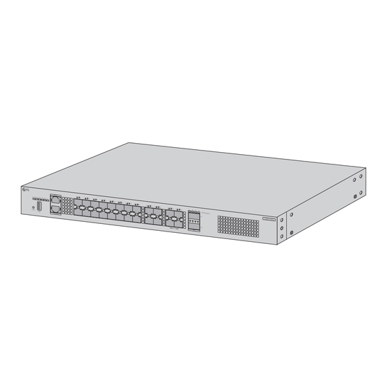
- Page 1 S5860-20SQ MANAGED L3 ENTERPRISE SWITCH MANAGED L3 ENTERPRISE-SWITCH SWITCH D'ENTREPRISE MANAGEABLE L3 管理型L�エンタプライズスイッチ Quick Start Guide V1.0 Quick-Start Anleitung Guide de Démarrage Rapide クイックスタートガイド...
- Page 2 Introduction Thank you for choosing Managed L3 Enterprise Switch. This guide is designed to familiarize you with the layout of the switch and describes how to mount it. S5860-20SQ Accessories S5860-20SQ (AC) Power Cord x2 Grounding Cable x1 Rubber Pad x4...
-
Page 3: Hardware Overview
S5860-20SQ (DC) DC Power Cable Set x2 Gounding Cable x3 Rubber Pad x4 Mounting Bracket x2 M4 Screw x8 NOTE: 1. S5860-20SQ switches have dust plugs delivered with them. Keep the dust plugs properly and use them to protect idle optical ports. 2. - Page 4 Ports Description SFP+ SFP+ ports for 1G/10G connection SFP28 SFP28 ports for 10G/25G connection QSFP+ QSFP+ ports for 40G or 4x10G connection MGMT An out-of-band Ethernet management port CONSOLE An RJ45 console port for serial management A USB management port for software and con guration backup and o ine software upgrade Front Panel Button FUNC...
- Page 5 LEDs State Description The system is powered o . 1. A system fault occurs. Solid Red 2. The temperature reaches the upper limit. STATUS Blinking Green Initialization is in progress. Solid Green The system works properly. Solid Amber The temperature reaches the threshold value. The power module is NOT in position.
-
Page 6: Installation Requirements
Installation Requirements Before you begin the installation, make sure that you have the following: Phillips screwdriver. Standard-sized, 19" wide rack with a minimum of 1U height available. Category 5e or higher RJ45 Ethernet cables, ber optical cables and a console cable for connecting network devices. -
Page 7: Mounting The Switch
Mounting the Switch Desk Mounting 1. Attach four rubber pads to the bottom. 2. Place the switch on a desk. Rack Mounting 1. Secure the mounting brackets to the two sides of the switch with supplied M4 screws. -
Page 8: Grounding The Switch
2. Attach the switch to the rack using four M6 screws and cage nuts. Grounding the Switch 1. Connect one end of the grounding cable to a proper earth ground, such as the rack in which the switch is mounted. 2. -
Page 9: Connecting The Sfp+ Ports
Connecting the SFP+ Ports 1. Plug the compatible SFP+ transceiver into the SFP+ port. 2. Connect one end of a ber optic cable to the ber transceiver. Then connect the other end of the cable to another ber device. Connecting the SFP28 Ports 1. -
Page 10: Connecting The Console Port
Connecting the QSFP+ Ports 1. Plug the compatible QSFP+ transceiver into the QSFP+ port. 2. Connect one end of a ber optic cable to the ber transceivers. Then connect the other end of the cable to another ber device. WARNING: Laser beams will cause eye damage. -
Page 11: Connecting The Usb Port
Connecting the MGMT Port 1. Connect one end of a standard RJ45 Ethernet cable to a computer. 2. Connect the other end of the cable to the MGMT port on the switch. Connecting the USB Port Insert the Universal Serial Bus (USB) ash disk into the USB port for software and con guration backup and o ine software upgrade. - Page 12 Connecting the Power (AC) 1. Plug the AC power cord into the power port on the back of the switch. 2. Connect the other end of the power cord to an AC power source. WARNING: Do not install the power cord while the power is on. Connecting the Power (DC) 1.
-
Page 13: Troubleshooting
NOTE: The S5860-20SQ switch is compatible with the P1D-K0150-B power module. WARNING: 1. Do not install the DC power cables while the power is on. 2. When installing or replacing the power module, the ground connection must always be made rst and disconnected last. Troubleshooting Power System Fault The indicator on the front panel of the host is OFF. -
Page 14: Online Resources
Product Warranty FS ensures our customers that for any damage or faulty items due to our workmanship, we will o er a free return within 30 days from the day you receive your goods. This excludes any custom-made items or tailored solutions. - Page 15 Einführung Vielen Dank, dass Sie sich für den Managed L3 Enterprise-Switch entschieden haben. Diese Anleitung soll Sie mit dem Aufbau der Switches vertraut machen und beschreibt, wie sie zu montieren sind. S5860-20SQ Zubehör S5860-20SQ (AC) Netzkabel x2 Erdungskabel x1 Gummiunterlage x4...
- Page 16 S5860-20SQ (DC) DC-Stromkabelsatz x2 Erdungskabel x3 Gummiunterlage x4 Montagehalterung x2 M4 Schraube x8 HINWEIS: 1. S5860-20SQ-Switches werden mit Staubschutzkappen geliefert. Bewahren Sie die Staubschutzkappen ordnungsgemäß auf, und verwenden Sie sie zum Schutz ungenutzter optischer Anschlüsse. 2. Das Zubehör kann von der Abbildung abweichen, bitte beachten Sie dies entsprechend.
- Page 17 Ports Beschreibung SFP+ SFP+-Ports für 1G/10G-Verbindungen SFP28 SFP28-Ports für 10G/25G-Verbindungen QSFP+ QSFP+-Ports für eine 40G- oder 4x10G-Verbindung MGMT Ein Out-of-Band-Ethernet-Verwaltungsanschluss CONSOLE Ein RJ45-Konsolenanschluss für die serielle Verwaltung Ein USB-Verwaltungsanschluss für Software- und Kon gurationssicherung und O ine-Software-Upgrade Taste an der Vorderseite FUNC Taste Beschreibung...
- Page 18 LEDs Zustand Beschreibung Das System ist ausgeschaltet. 1. ein Systemfehler auftritt. Durchgehend Rot 2. Die Temperatur erreicht den oberen Grenzwert. STATUS Blinkt Grün Die Initialisierung ist im Gange. Durchgehend Grün Das System arbeitet ordnungsgemäß. Durchgehend Die Temperatur erreicht den Schwellenwert. Bernstein Das Leistungsmodul ist NICHT in Position.
- Page 19 Installationsanforderungen Vergewissern Sie sich vor der Installation, dass Sie Folgendes haben Kreuzschlitzschraubendreher. 19"-Rack in Standardgröße mit einer Mindesthöhe von 1 HE verfügbar. RJ45-Ethernet-Kabel der Kategorie 5e oder höher, Glasfaserkabel und ein Konsolenkabel für den Anschluss von Netzwerkgeräten. Betriebsumgebung Betreiben Sie es nicht in einem Bereich, in dem die Umgebungstemperatur 50°C übersteigt.
- Page 20 Montage des Schalters Montage auf dem Schreibtisch 1. Befestigen Sie vier Gummipu er an der Unterseite. 2. Stellen Sie den Schalter auf einen Schreibtisch. Rack-Montage 1. Befestigen Sie die Montagehalterungen mit den mitgelieferten M4-Schrauben an den beiden Seiten des Switches.
- Page 21 2. Befestigen Sie den Switch mit vier M6-Schrauben und Kä gmuttern am Rack. Erdung des Switches 1. Schließen Sie ein Ende des Erdungskabels an eine geeignete Erdung an, z. B. an das Rack, in dem der Switch montiert ist. 2. Befestigen Sie die Erdungslasche mit der Schraube und den Unterlegscheiben am Erdungspunkt auf der Rückseite des Switches.
- Page 22 Anschließen der SFP+ Ports 1. Stecken Sie den kompatiblen SFP+-Transceiver in den SFP+-Port. 2. Schließen Sie ein Ende eines Glasfaserkabels an den Transceiver an. Schließen Sie dann das andere Ende des Kabels an ein anderes Glasfasergerät an. Anschließen der SFP28-Ports 1.
- Page 23 Anschließen der QSFP+ Ports 1. Stecken Sie den kompatiblen QSFP+-Transceiver in den QSFP+-Port. 2. Schließen Sie ein Ende eines Glasfaserkabels an die Glasfasertransceiver an. Schließen Sie dann das andere Ende des Kabels an ein anderes Glasfasergerät an. WARNUNG: Laserstrahlen können zu Augenschäden führen. Schauen Sie nicht ohne Augenschutz in die Bohrungen von Transceivern oder optischen Fasern.
- Page 24 Anschließen des MGMT-Ports 1. Schließen Sie ein Ende eines Standard-RJ45-Ethernetkabels an einen Computer an. 2. Schließen Sie das andere Ende des Kabels an den MGMT-Port des Switches an. Anschließen des USB-Ports Stecken Sie das USB-Flash-Laufwerk (Universal Serial Bus) in den USB-Port, um die Software und die Kon guration zu sichern und die Software o ine zu aktualisieren.
- Page 25 Anschließen der Stromversorgung (AC) 1. Stecken Sie das Netzkabel in den Netzanschluss auf der Rückseite des Switches. 2. Schließen Sie das andere Ende des Netzkabels an eine Stromversorgung an. WARNUNG: Schließen Sie das Netzkabel nicht an, während das Gerät eingeschaltet ist. Anschließen der Stromversorgung (DC) 1.
-
Page 26: Fehlerbehebung
HINWEIS: Der Schalter S5860-20SQ ist mit dem Leistungsmodul P1D-K0150-B kompatibel. WARNUNG: 1. Installieren Sie die Gleichstromkabel nicht, während das Gerät eingeschaltet ist. 2. Bei der Installation oder dem Austausch des Leistungsmoduls muss die Erdverbindung immer zuerst hergestellt und zuletzt getrennt werden. Fehlerbehebung Fehler im Stromversorgungssystem Die Anzeige an der Vorderseite des Hosts ist AUS. - Page 27 Kontakt https://www.fs.com/de/contact_us.html Produktgarantie FS garantiert seinen Kunden, dass wir bei Schäden oder fehlerhaften Artikeln, die auf unsere Verarbeitung zurückzuführen sind, eine kostenlose Rückgabe innerhalb von 30 Tagen nach Erhalt der Ware anbieten. Dies gilt nicht für Sonderanfertigungen oder maßgeschneiderte Lösungen.
- Page 28 Introduction Nous vous remercions d'avoir choisi le Switch d'Entreprise Manageable L3. Ce guide est conçu pour vous familiariser avec la con guration du switch et décrit comment procéder à son déploiement. S5860-20SQ Accessoires S5860-20SQ (AC) Câble d'Alimentation x2 Câble de Mise à la Terre x1...
-
Page 29: Présentation Du Matériel
S5860-20SQ (DC) Lot de Câble d'Alimentation DC x2 Câble de Mise à la Terre x3 Pad en Caoutchouc x4 Support de Montage x2 Vis M4 x8 NOTE : 1. Les Switchs S5860-20SQ sont livrés avec des bouchons anti- poussière. Conservez-les correctement et utilisez-les pour protéger les ports optiques inactifs. - Page 30 Ports Description SFP+ Ports SFP+ pour connection 1G/10G SFP28 Ports SFP28 pour connection 10G/25G QSFP+ Ports QSFP+ pour connection 40G ou 4x 10G MGMT Un port de gestion Ethernet hors bande CONSOLE Un port de console RJ45 pour la gestion en série Un port de gestion USB pour la sauvegarde du logiciel et de la con guration et la mise à...
- Page 31 État Description Éteint Le système est sous tension éteint. 1. Un défaut du système se produit. Rouge 2. La température atteint la limite supérieure. STATUS Vert Clignotant L'initialisation est en cours. Vert Le système fonctionne correctement. Ambré La température atteint la valeur seuil. Éteint Le module d'alimentation n'est PAS en position.
-
Page 32: Conditions D'installation
Conditions d'Installation Avant l'installation, assurez-vous que vous disposez des éléments suivants : Phillips screwdriver. Standard-sized, 19" wide rack with a minimum of 1U height available. Category 5e or higher RJ45 Ethernet cables, ber optical cables and a console cable for connecting network devices. -
Page 33: Installation Sur Bureau
Installation du Switch Installation sur Bureau 1. Fixez quatre pads en caoutchouc à la base du switch. 2. Placez le switch sur un bureau. Installation en Rack 1. Fixez les supports de montage sur les deux côtés du switch à l'aide des vis M4 fournies. - Page 34 2. Fixez le switch au rack à l'aide de quatre vis M6 et d'écrous à cage. Mise à la Terre du Switch 1. Connectez l'une des extrémités du câble de mise à la terre à une terre appropriée, telle que le rack dans lequel le commutateur est installé. 2.
- Page 35 Connexion des Ports SFP+ 1. Branchez l'émetteur-récepteur SFP+ compatible dans le port SFP+. 2. Connectez une extrémité d'une jarretière optique à l'émetteur-récepteur à bre. Connectez ensuite l'autre extrémité de la jarretière optique à un autre dispositif à bre optique. Connexion des Ports SFP28 1.
- Page 36 Connexion des Ports QSFP+ 1. Branchez l'émetteur-récepteur QSFP+ compatible dans le port QSFP+. 2. Connectez une extrémité d'une jarretière optique à l'émetteur-récepteur à bre. Connectez ensuite l'autre extrémité de la jarretière optique à un autre dispositif à bre optique. AVERTISSEMENT : Les faisceaux laser provoquent des lésions oculaires.
- Page 37 Connexion du Port MGMT 1. Connectez une extrémité d'un câble Ethernet RJ45 standard à un ordinateur. 2. Connectez l'autre extrémité du câble au port MGMT du switch. Connexion du Port USB Insérez le disque ash USB (Universal Serial Bus) dans le port USB pour la sauvegarde du logiciel et de la con guration et la mise à...
- Page 38 Branchement de l'Alimentation (AC) 1. Branchez le câble d'alimentation AC sur le port d'alimentation de l'arrière du switch. 2. Branchez l'autre extrémité du câble d'alimentation à une source d'alimentation en courant alternatif. AVERTISSEMENT : Ne pas branchez le câble d'alimentation lorsque l'interrupteur est en position de marche.
-
Page 39: Dépannage
NOTE : Le switch S5860-20SQ est compatible avec le module d'alimentation P1D-K0150-B. AVERTISSEMENT : 1. Ne pas installez les câbles d'alimentation DC lorsque l'appareil est sous tension. 2. Lors de l'installation ou du remplacement du module d'alimentation, la connexion à la terre doit toujours être e ectuée en premier et déconnectée en dernier. -
Page 40: Garantie Du Produit
Contactez-nous Garantie du Produit FS garantit à ses clients que tout article endommagé ou défectueux en raison de sa fabrication pourra être retourné gratuitement dans un délai de 30 jours à compter de la date de réception de la marchandise. Cette garantie ne s'applique pas aux articles fabriqués sur mesure ou aux solutions personnalisées. - Page 41 イントロダクション この度は、管理型L�エンタプライズスイッチをお選び頂き、誠にありがとうございます。 このガイドは、スイッチのレイアウトを理解し、ネットワークにスイッチを導入する方法 を説明するためのものです。 S����-��SQ アクセサリー S����-��SQ (AC) 電源コードx� 接地ケーブルx� ゴムパッドx� マウントブラケットx� M�ネジx�...
- Page 42 S����-��SQ (DC) DC電源ケーブルセットx� 接地ケーブルx� ゴムパッドx� マウントブラケットx� M�ネジx� 注:�. S����-��SQスイッチには防塵プラグが付属しています。ダストプラグは 適切に保管し、アイドル状態の光ポートを保護するために使用してください。 �. アクセサリーはイラストと異なる場合がありますので、ご注意ください。 �. この電源コードは他のデバイスでは使用できません。また、このデバイスでは 他の電源コードを使用しないでください。 ハードウェア概要 フロントパネルポート MGMT SFP+ SFP�� USB CONSOLE QSFP+...
- Page 43 ポート 説明 SFP+ �G/��G接続用SFP+ポート SFP�� ��G/��G接続用SFP��ポート QSFP+ ��G/�x��G接続用QSFP+ポート MGMT 帯域外イーサネット管理ポート CONSOLE シリアル管理用RJ��コンソールポート ソフトウェアと構成のバックアップとオフラインソフトウェアアップグ レード用のUSB管理ポート フロントパネルボタン FUNC ボタン 説明 FUNCボタンを�秒以上押し、さらに��秒待って、スイッチを再起動しま FUNC す。 フロント/バックパネルLED S����-��SQ SFP+ SFP�� STATUS QSFP+ MGMT PWR� PWR� S����-��SQ (DC) 電源状態...
- Page 44 状態 説明 消灯 システムの電源が切れています。 �. システム障害が発生します。 点灯(赤) �. 温度が上限に達しています。 STATUS 点減(緑) 初期化が進行中です。 点灯(緑) システムは正常に動作しています。 点灯 温度がしきい値に達しました。 (アンバー) 消灯 電源モジュールが所定の位置にありません。 PWR�/PWR� 点灯(緑) 電源モジュールは正常に動作しています。 点灯(赤) 電源障害が発生します。 点灯(緑) ファンは正常に動作しています。 �. ファン障害が発生しました。 点灯(赤) �. ファンのモデルがシステムと一致しません。 �. いくつかのファンが所定の位置にありません。 消灯 MGMTポートが接続されていません。 MGMT 点灯(緑) MGMTポートが接続されています。 点減(緑) MGMTポートはデータを送信または受信しています。 消灯...
- Page 45 インストール要件 インストールを開始する前に、以下のことを確認してください。 プラスドライバー。 �U以上の高さが利用可能な標準サイズの��インチ幅のラック。 ネットワークデバイスを接続するためのカテゴリ�eまたはそれ以上のRJ��イーサネッ トケーブル、光ファイバケーブルとコンソールケーブル。 設置環境 周囲温度が��℃を超える場所では使用しないでください。 設置場所は十分に換気する必要があります。 スイッチは、デバイスから側面まで少なくとも�U (��.��mm)離して設置する必要があ ります。 危険な状況を避けるために、スイッチが水平で安定していることを確認してください。 ほこりの多い環境に装置を設置しないでください。 水漏れ、水滴、結露、湿気のない場所に設置してください。 ラックと作業プラットフォームが十分に接地されていることを確認してください。...
- Page 46 スイッチの取り付け デスクマウント �. 底に�つのゴムパッドを取り付けます。 �. スイッチを机の上に置きます。 ラックマウント �. 付属のネジを使用して、取り付けブラケットをスイッチの両側に固定します。...
- Page 47 �. M�ネジとケージナットを使用して、スイッチをラックに取り付けます。 スイッチの接地 �. 接地ケーブルの一方の端を、スイッチが取り付けられているラックなどの適切なアース に接続します。 �. ワッシャとネジを使用して、接地ラグをスイッチのバックパネルの接地点に固定します。 注意:すべての電源接続が切断されていない限り、アース接続を取り外さないで ください。...
- Page 48 SFP+ポートの接続 �. 互換性のあるSFP+モジュールをSFP+ポートに差し込みます。 �. 光ファイバケーブルをファイバモジュールに接続します。次に、ケーブルのもう一方の 端を別のファイバデバイスに接続します。 SFP��ポートの接続 �. 互換性のあるSFP��モジュールをSFP��ポートに差し込みます。 �. 光ファイバケーブルをファイバモジュールに接続します。次に、ケーブルのもう一方の 端を別のファイバデバイスに接続します。...
- Page 49 QSFP+ポートの接続 �. 互換性のあるQSFP+モジュールをQSFP+ポートに差し込みます。 �. 光ファイバケーブルをファイバモジュールに接続します。次に、ケーブルのもう一方の 端を別のファイバデバイスに接続します。 警告:レーザー光線は目に損傷を与える可能性があります。目を保護せずに光モ ジュールや光ファイバの穴をのぞきこまないでください。 コンソールポートの接続 �. コンソールケーブルのRJ��コネクタをスイッチのRJ��コンソールポートに挿入します。 �. コンソールケーブルのDB�メスコネクタをコンピュータのシリアルポートに接続します。...
- Page 50 MGMTポートの接続 �. 標準のRJ��イーサネットケーブルの一端をコンピュータに接続します。 �. ケーブルのもう一方の端をスイッチのMGMTポートに接続します。 USBポートの接続 USB(ユニバーサル・シリアル・バス)フラッシュ・ディスクをUSBポートに挿入し、ソフト ウェアと構成のバックアップ、およびオフラインでのソフトウェアとアップグレードを行 います。...
- Page 51 電源の接続(AC) �. AC電源コードをスイッチの背面にある電源ポートに差し込みます。 �. 電源コードのもう一方の端をAC電源に接続します。 警告:電源が入った状態で電源コードを取り付けないでください。 電源の接続(DC) �. プラス/マイナスのDC電源コードを接点+と-に挿入します。 �. ワイヤが緩まないように、ワイヤクランプネジを締めてください。...
- Page 52 注:S����-��SQスイッチは、P�D-K����-B電源モジュールと互換性があります。 警告:�. 電源が入った状態でDC電源コードを取り付けないでください。 �.電源モジュールの取り付けまたは交換を行う場合は、必ず最初にアース接続を 行い、最後に切断する必要があります。 トラブルシューティング 電源システムの障害 ホストのフロントパネルのインジケーターが消灯しています。ファンモジュールのステー タスインジケーターが消灯し、ファンが動作しません。電源モジュールのパネル上のイン ジケーターが消灯し、ファンが動作しません。以上の問題がある場合は、以下の点をご確 認ください。 まず、電源モジュールの電源コードを外します。 �. キャビネットのケーブルが正しく接続されているかどうかを確認します。 �. キャビネットの電源ソケットと電源モジュールの接続が緩いかどうかを確認します。 �. 電源モジュールが正しく取り付けられているかどうかを確認します。 スイッチのリモート接続がうまくいかない �. pingでネットワークの接続性をテストします。 �. ネットワークに到達できる場合は、スイッチの再起動をお試しください。 �. 対応するサービスが有効になっているかどうかを確認します。 ポートが動作していない、LEDインジケーターが消灯している �. スイッチポートがシャットダウンしない状態であることを確認します。 �. スイッチがDDM情報を読み取れるかどうか確認してください。 �. ポートスピードの設定が正しいかどうか確認してください。 �. スイッチのケーブルをループさせてみてください。...
- Page 53 設定端末に何も表示されない 電源投入後、設定用端末に何も表示されない場合は、まず以下のことを確認してみてくだ さい。 �. シリアルポートケーブルが正しく接続されているかどうか。 �. HyperTerminalの構成パラメータが正しく設定されているかどうか。 設定端末にエラーコードが表示される 設定端末でエラーコードが表示される場合は、端末(HyperTerminalなど)のパラメータが正 しく設定されていない可能性があります。端末(HyperTerminalなど)のパラメータをご確認 ください。 オンラインリソース ダウンロード https://www.fs.com/jp/products_support.html ヘルプセンター https://www.fs.com/jp/service/fs_support.html お問い合わせ https://www.fs.com/jp/contact_us.html 製品保証 FSでは、弊社の製造技術による破損や不良品については、商品をお受け取りになった日か ら��日以内であれば、無料で返品を承ります。ただし、これにはカスタム製品やオーダー メイドは含まれません。 保証:この製品は、材料または製造上の欠陥に対して�年間の限定保証を提供し ます。保証の詳細については、次のサイトでご確認ください: https://www.fs.com/jp/policies/warranty.html 返品:返品したい場合は、返品方法に関する情報が次のサイトにご覧ください: https://www.fs.com/jp/policies/day_return_policy.html...
-
Page 54: Compliance Information
Compliance Information S5860-20SQ (AC)/S5860-20SQ (DC) Note: This equipment has been tested and found to comply with the limits for a Class A digital device, pursuant to part 15 of the FCC Rules. These limits are designed to provide reasonable protection against harmful interference when the equipment is operated in a commercial environment. - Page 55 2014/35/EU, 2011/65/EU und (EU)2015/863 konform ist. Eine Kopie der EU-Konformitätserklärung nden Sie unter www.fs.com/de/company/quality_control.html. FS.COM GmbH déclare par la présente que ce dispositif est conforme à la Directive 2014/30/EU, 2014/35/EU, 2011/65/EU et (EU)2015/863. Une copie de la Déclaration de Conformité de l'UE est disponible à l'adresse suivante https://www.fs.com/fr/company/quality_control.html.
- Page 56 2011/65/EU und (EU)2015/863 konform ist. Eine Kopie der EU-Konformitätserklärung nden Sie unter www.fs.com/de/company/quality_control.html. FS.COM GmbH déclare par la présente que ce dispositif est conforme à la Directive 2014/30/EU, 2011/65/EU et (EU)2015/863. Une copie de la Déclaration de Conformité de l'UE est disponible à l'adresse suivante https://www.fs.com/fr/company/quality_control.html.
- Page 57 Do not dispose of WEEE as unsorted municipal wasteand have to collect such WEEE separately. Q.C. PASSED Copyright © 2023 FS.COM All Rights Reserved.
Need help?
Do you have a question about the L3 and is the answer not in the manual?
Questions and answers