Table of Contents
Advertisement
Available languages
Available languages
Quick Links
Advertisement
Chapters
Table of Contents

Related Manuals for Fronius String Control 100/12 MET


Summary of Contents for Fronius String Control 100/12 MET
- Page 1 / Battery Charging Systems / Welding Technology / Solar Electronics Bedienungsanleitung Fronius String Control 100/12 MET Anlagenüberwachung Operating Instructions System monitoring 42,0410,1940 001-05022013...
- Page 3 Einleitung Wir danken Ihnen für Ihr entgegengebrachtes Vertrauen und gratulieren Ihnen zu Ihrem technisch hochwertigen Fronius Produkt. Die vorliegende Anleitung hilft Ihnen, sich mit diesem vertraut zu machen. Indem Sie die Anleitung sorgfältig lesen, lernen Sie die viel- fältigen Möglichkeiten Ihres Fronius-Produktes kennen. Nur so können Sie seine Vorteile bestmöglich nutzen.
-
Page 5: Table Of Contents
Fronius String Control 100/12 montieren ....................Solarmodul-Stränge an der Fronius String Control 100/12 anschließen ........... Sicherheit .............................. Hinweise zum Anschließen der Solarmodul-Stränge an der Fronius String Control 100/12 ....Anschlussbelegung bei geerdeten Solarmodulen................. Beispiel für Anschlussbelegung bei geerdeten Solarmodulen.............. Solarmodul-Stränge an der Fronius String Control 100/12 anschließen .......... - Page 6 Sicherheit .............................. Fronius String Control 100/12 schließen....................Einstellungen ............................. Allgemeines ............................Erste Schritte ............................Mögliche Einstellungen für die Fronius String Control 100/12 .............. Stränge pro Messkanal ......................... Max. Ertragsabweichung ........................Schwellwert............................Anzeige der Daten und Statusmeldungen ....................Anzeige der Daten ..........................
-
Page 7: Sicherheitsvorschriften
Sicherheitsvorschriften Allgemeines Das Gerät ist nach dem Stand der Technik und den anerkannten sicherheits- technischen Regeln gefertigt. Dennoch drohen bei Fehlbedienung oder Miss- brauch Gefahr für Leib und Leben des Bedieners oder Dritte, das Gerät und andere Sachwerte des Betreibers, die effiziente Arbeit mit dem Gerät. - Page 8 Qualifiziertes Per- Die Serviceinformationen in dieser Bedienungsanleitung sind nur für qualifi- sonal ziertes Fachpersonal bestimmt. Ein elektrischer Schlag kann tödlich sein. Führen Sie keine anderen als die in der Dokumentation angeführten Tätig- keiten aus. Das gilt auch, wenn sie dafür qualifiziert sind. Sämtliche Kabel und Leitungen müssen fest, unbeschädigt, isoliert und aus- reichend dimensioniert sein.
- Page 9 ESD-Schutzmaß- Gefahr einer Beschädigung elektronischer Komponenten durch elektrische nahmen Entladung. Bei Austausch und Installation der Komponenten geeignete ESD- Schutzmaßnahmen treffen. Sicherheitsmaß- Das Gerät nur betreiben, wenn alle Schutzeinrichtungen voll funktionstüchtig nahmen im Nor- sind. Sind die Schutzeinrichtungen nicht voll funktionsfähig, besteht die Ge- malbetrieb fahr für Leib und Leben des Bedieners oder Dritte,...
-
Page 10: Allgemeines
Mittelwert, wird eine Statusmeldung an den Fronius Datalogger ausgegeben. Die zulässige Abweichung vom Mittelwert ist frei definierbar. Wechselrichter Die Fronius String Control 100/12 ist ausschließlich für den Betrieb mit folgenden Wech- selrichtern geeignet: Fronius IG 300 / 390 / 400 / 500... -
Page 11: Lieferumfang
Lieferumfang 1 Fronius String Control 100/12 (im Metallgehäuse) 2 metrische Verschraubungen M32 inkl. Gegenmuttern 24 metrische Verschraubungen M16 inkl. Gegenmuttern 10 Blindverschraubungen M16 1 metrische Verschraubung M20 inkl. Gegenmutter 1 metrische Blindverschraubung M20 1 metrische Verschraubung M25 inkl. Gegenmutter 1 Gummieinsatz M25 2 Kunststoff-Bolzen 1 Silikonschlauch Ø... -
Page 12: Verwendete Abkürzungen Und Bezeichnungen
Solarmodul-Strang besteht jeweils aus einem DC+ Kabel und einem DC- Kabel. Warnhinweise am An der Fronius String Control 100/12 befinden sich Warnhinweise und Sicherheitssym- Gerät bole. Diese Warnhinweise und Sicherheitssymbole dürfen weder entfernt noch übermalt werden. Die Hinweise und Symbole warnen vor Fehlbedienung, woraus schwerwiegende Personen- und Sachschäden resultieren können. - Page 13 Text der Warnhinweise: WARNUNG! Ein elektrischer Schlag kann tödlich sein. Gefahr durch DC-Spannung von den Solarmodulen. Mehr als eine Versorgungsquelle. Vor Wartungsarbeiten alle Versorgungsquellen trennen. Vor dem Öffnen des Gerätes dafür sorgen, dass Eingangsseite und Ausgangsseite vor dem Gerät spannungsfrei sind! Gefährliche Spannung durch Solarmodule, die Licht ausgesetzt sind.
-
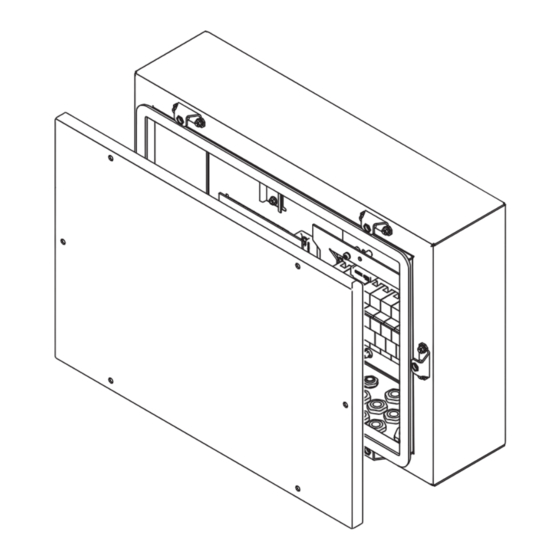
Page 14: Gerätebeschreibung
Bedienungsanleitungen der Systemkomponenten, insbesondere Sicherheitsvorschriften Gerätebeschrei- bung Gehäuse (8) (9) Fronius String Control 100/12 - Vorderansicht Fronius String Control 100/12 - Schrägansicht von oben Pos. Bezeichnung Kabeleingang für metrische Verschraubungen M16 (für DC-Kabel ‘IN’) Kabeldurchmesser 3 - 7 mm Kabeleingang für metrische Verschraubungen M16... -
Page 15: Gerätebeschreibung Geräteinneres
WICHTIG! Metrische Verschraubungen und Blindverschraubungen sind bei Auslieferung nicht an der Fronius String Control 100/12 montiert, sondern werden nur beigelegt. Gerätebeschrei- bung Geräteinne- (12) (11) (10) Fronius String Control 100/12 - Geräteinneres Pos. Bezeichnung Hutschiene zur Montage eines handelsüblichen Überspannungsschutz Messkanal 1 RJ 45 Anschlüsse für Datenkommunikations-Kabel... -
Page 16: Metrische Verschraubungen An Der Fronius String Control 100/12 Montieren
Metrische Verschraubungen an der Fronius String Control 100/12 montieren Allgemeines Metrische Verschraubungen entsprechend der Anzahl der vorhandenen Solarmodul- Stränge einsetzen, in leere Positionen Blindverschraubungen einsetzen. Reihenfolge beim Einsetzen der metrischen Verschraubungen beachten: von unten nach oben und von links nach rechts. -
Page 17: Anzugsmomente Für Metrische Verschraubungen
Ver- 3,0 Nm 2,0 Nm schraubungen 6,0 Nm 4,0 Nm 8,0 Nm 5,0 Nm 10,0 Nm 6,5 Nm Die Verschraubung erfolgt an der Innenseite der Fronius String Control 100/12. Das Anzugsmoment für die Zugentlastung gilt bei angeschlossenen Kabeln. -
Page 18: Fronius String Control 100/12 Montieren
Je nach Untergrund sind unterschiedliche Dübel und Schrauben für die Montage der Froni- bel und Schrau- us String Control 100/12 erforderlich. Dübel und Schrauben sind daher nicht im Lieferum- fang der Fronius String Control 100/12 enthalten. Der Monteur ist für die richtige Auswahl von passenden Dübeln und Schrauben selbst verantwortlich. Standortwahl... -
Page 19: Montagelage
Bei vertikaler und schräger Monatagelage müssen die Kabelein- 0-90° und -ausgänge nach unten zeigen. Fronius String HINWEIS! Die Montage der Fronius String Control 100/12 darf ausschließlich an Control 100/12 den dafür vorgesehenen Montagelaschen erfolgen. montieren Keinesfalls Bohrungen im Gehäuse anbringen! -
Page 21: Solarmodul-Stränge An Der Fronius String Control 100/12 Anschließen
HINWEIS! Um ein problemloses Anschließen der DC-Kabeln an den Anschluss- klemmen zu gewährleisten, eine Mindestlänge der DC-Kabel von 330 mm be- rücksichtigen (gemessen von der inneren Unterkante der Fronius String Control 100/12). HINWEIS! Reihenfolge beim Einführen und Anschließen der DC-Kabel beach- ten: von unten nach oben und von innen nach außen. -
Page 22: Anschlussbelegung Bei Geerdeten Solarmodulen
Beispiel für An- schlussbelegung bei geerdeten So- larmodulen B‘ A‘ B‘ A‘ Belegung bei Solarmodul-Erdung am Minuspol Belegung bei Solarmodul-Erdung am Pluspol Solarmodul- Stränge an der Fronius String Control 100/12 anschließen Anzugsmoment 2,0 Nm Anzugsmoment 1,5 Nm Anzugsmoment 2,0 Nm... -
Page 23: Abschließende Tätigkeiten
Abschließende HINWEIS! Tätigkeiten Mit den DC-Kabeln der Solarmodule außerhalb der Geräte eine Schleife bil- den! Geeignete Zugentlastung vorsehen, dass nicht das volle Kabelgewicht auf die Gerätewand einwirkt. DC IN Schlaufenbildung bei vertikaler Montagelage DC IN Schlaufenbildung bei horizontaler Montagelage... -
Page 24: Fronius String Control 100/12 Mit Dem Wechselrichter Verbinden
Fronius String Control 100/12 mit dem Wechselrich- ter verbinden Sicherheit WARNUNG! Ein elektrischer Schlag kann tödlich sein. Gefahr durch DC-Span- nung von den Solarmodulen. Vor allen Anschlussarbeiten dafür sorgen, dass Eingangsseite und Aus- gangsseite vor dem Gerät spannungsfrei sind! Sämtliche Anschlussarbeiten dürfen nur von lizenzierten Elektro-Installateu- ren durchgeführt werden! -
Page 25: Fronius String Control 100/12 Mit Dem Wechselrichter Verbinden
Wechsel- richter verbinden HINWEIS! Beim Anschließen folgende Punkte beachten: Ist eine Solarmodul-Erdung erforderlich oder vorhanden? Falls ja, Besonderheiten der jeweiligen Solarmodul-Erdung berücksichtigen Bei vorhandener Solarmodul-Erdung empfiehlt Fronius, Strangsicherungen immer im nichtgeerdeten Zweig einzusetzen. DC-Kabel ‘OUT’ polrichtig am Wechselrichter anschließen... -
Page 26: Kriterien Zur Richtigen Auswahl Von Strangsicherungen
< 2,4 x I >/= max. Eingangsspannung des verwendeten Wechselrichters: Fronius CL 36.0 / 48.0 / 60.0 ... 600 V DC Fronius IG Plus / IG Plus V ... 600 V Sicherungsdimensionen: Durchmesser 10 x 38 mm Nenn-Stromwert der Sicherung Kurzschluss-Strom bei Standard-Testbedingungen (STC) gemäß... -
Page 27: Anwendungsbeispiel
Anwendungsbei- z.B.: Maximaler Kurzschluss-Strom (I ) des Solarmodules = 5,75 A spiel Entsprechend der Kriterien zur richtigen Auswahl von Strangsicherungen muss der Nenn- Stromwert der Sicherung größer sein als das 1,5-fache und kleiner als das 2,0-fache des Kurzschluss-Stromes: 5,75 A x 1,5 = 8,625 A 5,75 A x 2,0 = 11,5 A gemäß... -
Page 28: Strangsicherungen Einsetzen
Strangsicherungen einsetzen Sicherheit WARNUNG! Ein elektrischer Schlag kann tödlich sein. Gefahr durch DC-Span- nung von den Solarmodulen. Vor allen Anschlussarbeiten dafür sorgen, dass Eingangsseite und Aus- gangsseite vor dem Gerät spannungsfrei sind! Sicherungen nicht unter Last entnehmen oder einsetzen! Sämtliche Anschlussarbeiten dürfen nur von lizenzierten Elektro-Installateu- ren durchgeführt werden! Beachten Sie die Sicherheitsvorschriften in dieser Bedienungsanleitung. -
Page 29: Datenkommunikations-Kabel An Der Fronius String Control 100/12 Anschließen
Datenkommunikations-Kabel an der Fronius String Control 100/12 anschließen Anbindungsmög- Die Anbindung der Fronius String Control 100/12 in das Solar Net kann über 2 Möglich- lichkeiten keiten erfolgen: über vorkonfektionierte Datenkommunikations-Kabel mit RJ 45 Steckern Empfehlung für die Kabel: Kabelgröße CAT 5, 1:1 Kabel über mehradrige Datenkommunikations-Kabel... -
Page 30: Konfigurationsbeispiel
OUT 1 +12V OUT 1 +12V +12V +12V +12V Wechselrichter mit Fronius Com Card Fronius String Control 100/12 Fronius Datalogger Abschluss-Stecker Sicherheit WARNUNG! Ein elektrischer Schlag kann tödlich sein. Gefahr durch DC-Span- nung von den Solarmodulen. Vor allen Anschlussarbeiten dafür sorgen, dass Eingangsseite und Aus- gangsseite vor dem Gerät spannungsfrei sind! -
Page 31: Rj 45 Datenkommunikations-Kabel An Der Fronius String Control 100/12 Anschließen
Silikonschlauch Ø 25 x 510 mm HINWEIS! Vorgehensweise, wenn nur 1 Datenkommunikations-Kabel an der Fronius String Control 100/12 angeschlossen wird (z.B., wenn die Fronius String Controll 100/12 die letzte Komponente in einem Solar Net ist): Am freien RJ 45 Anschluss den Abschluss-Stecker anstecken; der Ab- schluss-Stecker ist im Lieferumfang von jedem Fronius Datalogger enthal- ten. -
Page 32: Mehradrige Datenkommunikations-Kabel An Der Fronius String Control 100/12 Anschließen
6 mm werden beide Kabel wie beim RJ 45 Kabel durch den Gummieinsatz und tions-Kabel an die dafür vorgesehene Öffnung geführt. der Fronius St- ring Control 100/ Die folgenden Arbeitsschritte gelten für Datenkommunikations-Kabel mit einem Durch- 12 anschließen messer bis max. - Page 33 Anzugsmoment 5 Nm HINWEIS! Vorgehensweise, wenn nur 1 mehradriges Datenkommunikations-Ka- bel an der Fronius String Control 100/12 angeschlossen wird (z.B., wenn die Fronius String Controll 100/12 die letzte Komponente in einem Solar Net ist): Ist das Datenkommunikations-Kabel an den „IN“-Anschlussklemmen ange- schlossen, den Abschluss-Stecker am „OUT“-RJ 45 Anschluss anstecken.
-
Page 34: Überstrom- Und Unterspannungs-Abschaltung
Überstrom- und Unterspannungs-Abschaltung Allgemeines Die Fronius String Control 100/12 verfügt über eine Abschaltfunktion, die die Energiever- sorgung im Solar Net unterbricht: bei Überstrom, z.B. im Fall eines Kurzschlusses bei Unterspannung Funktionsprinzip Die Überstrom- und Unterspannungs-Abschaltung ist nicht von der Stromfluss-Richtung abhängig. -
Page 35: Energieversorgung Manuell Wiederherstellen
In diesem Fall ist eine externe Energieversorgung der DATCOM-Komponenten mittels ex- ternem Netzteil erforderlich. Energieversor- Das manuelle Wiederherstellen der Energieversorgung unterstützt den Installateur bei der gung manuell Fehlersuche und Fehlerbehebung im Fronius Solar Net. wiederherstellen Jumper-Positionen: automatisches Wiederherstellen der Energieversorgung... -
Page 36: Externe Energieversorgung Anschließen
Externe Energieversorgung anschließen Allgemeines Die Energieversorgung der Fronius String Control 100/12 erfolgt über das Solar Net. In Verbindung mit zusätzlichen DATCOM-Komponenten oder wenn die Datenkommunika- tions-Kabel eine Länge von 100 m überschreiten, kann die Energieversorgung über das Solar Net nicht mehr ausreichen. Für diesen Fall ist ein externes Netzteil vefügbar. - Page 37 Falls keine Öffnung im Gummieinsatz frei ist, zusätzliche Ausnehmung für das Netz- teil-Kabel in den Gummieinsatz schneiden Datenkommunikations-Kabel und Netzteil-Kabel in den Gummieinsatz einsetzen Gummieinsatz mit den Kabeln in die metrische Verschraubung einsetzen Metrische Verschraubung festziehen...
-
Page 38: Adresse Einstellen
Beachten Sie die Sicherheitsvorschriften in dieser Bedienungsanleitung. Allgemeines Das Solar Net ermöglicht den gleichzeitigen Betrieb von bis zu 200 Fronius String Control 100/12. Die Unterscheidung der einzelnen Fronius String Controls erfolgt durch Zuweisen einer Adresse. Das Einstellen der Adresse von 0 - 199 erfolgt am Adress-Schalter: Jumper für die Hunderter-Stelle... -
Page 39: Fronius String Control 100/12 Schließen
Fronius String Control 100/12 schließen Sicherheit WARNUNG! Ein elektrischer Schlag kann tödlich sein. Gefahr durch DC-Span- nung von den Solarmodulen. Vor allen Anschlussarbeiten dafür sorgen, dass Eingangsseite und Aus- gangsseite vor dem Gerät spannungsfrei sind! Sämtliche Anschlussarbeiten dürfen nur von lizenzierten Elektro-Installateu- ren durchgeführt werden! -
Page 40: Einstellungen
Einstellungen Allgemeines Die Einstellungen für die Fronius String Control 100/12 erfolgen in der Software „Fronius Solar.access“. Erste Schritte Software Fronius Solar.access am PC installieren Administration / Anlage anlegen Anlagen / [Name der Anlage] / Einstellungen / String Control Mögliche Einstel- Auswahl der Nummer (Adresse) der einzustellenden Fronius String Control 100/12 lungen für die... -
Page 41: Max. Ertragsabweichung
Mittelwert aller Messkanäle und vergleicht den Strom jedes Messkanals mit dem Mit- telwert aller Messkanäle. Registriert die Fronius String Control 100/12 eine Abweichung eines Messkanals von diesem Mittelwert, wird eine Statusmeldung an den Fronius Data- logger ausgegeben. Im Eingabefeld „Max. Ertragsabweichung“ definieren Sie, ab welcher Abweichung in % ein Messkanal als fehlerhaft eingestuft werden soll. -
Page 42: Anzeige Der Daten Und Statusmeldungen
Statusmeldung. Ein Versenden der Statusmeldungen als SMS, Fax oder E-Mail ist mög- lich. Näheres dazu entnehmen Sie der Bedienungsanleitung DATCOM Detail. Die Servicecodes der Fronius String Control 100/12 lauten State 901 bis 902. Diese Se- vicecodes beschreiben eine unzulässige Abweichung der Messkanäle 1 und 2. -
Page 43: Statusdiagnose Und Fehlerbehebung
Jumper auf manuelle Wiederherstellung der Energiever- sorgung umsetzen Leitungen, Anschlüsse und Versorgung überprüfen: der Fehler ist ab der ersten Fronius String Control 100/12 in OUT-Richtung zu finden, bei der die LED ‘X’ (1) rot leuchtet oder keine Stromversorgung vorhanden ist... -
Page 44: Strangsicherungen Tauschen, Wartung
Sicherungen nicht unter Last wechseln! Vorbereitung Verbindung zu den AC-Zuleitungen mittels AC-Trenneinrichtung für den Wechselrich- ter unterbrechen Solarmodul-Stränge zur Fronius String Control 100/12 unterbrechen Ein deutlich lesbares und verständliches Warnschild gegen Wiedereinschalten und Wiederzusammenführen von geöffneten / unterbrochenen Verbindungen anbringen Solarmodul-Stränge auf Spannungsfreiheit überprüfen Solarmodul-Stränge kurzschließen... -
Page 45: Abschließende Tätigkeiten
Abschließende Deckel montieren Tätigkeiten Kurzschluss der Solarmodul-Stränge aufheben Solarmodul-Stränge zur Fronius String Control 100/12 schließen Verbindung zu den AC-Zuleitungen mittels AC-Trenneinrichtung für den Wechselrich- ter wieder herstellen Wartung HINWEIS! Bei horizontaler Montagelage: sämtliche Verschraubungen jährlich auf festen Sitz überprüfen! - Page 47 Thank you for the trust you have placed in our company and congratulations on buying this high-quality Fronius product. These instructions will help you familiarize yourself with the product. Reading the instructions carefully will enable you to learn about the many different features it has to offer.
- Page 49 Connecting Solar Module Strings to the Fronius String Control 100/12 ............ Safety..............................Notes for Connecting Solar Module Strings to the Fronius String Control 100/12 ....... Terminal assignment for grounded solar modules................Example of terminal assignment for grounded solar modules ..............
- Page 50 Closing the Fronius String Control 100/12 .................... Settings ..............................General ..............................Initial Steps ............................Possible Settings for the Fronius String Control 100/12 ............... Strings per Measuring Channel ......................Max. Energy Deviation.......................... Threshold .............................. Display of Data and Status Messages .......................
-
Page 51: Safety Rules
Safety rules General The device is manufactured using state-of-the-art technology and according to recognized safety standards. If used incorrectly or misused, however, it can cause injury or death to the operator or a third party, damage to the device and other material assets belonging to the operator, inefficient operation of the device All persons involved in commissioning, maintaining and servicing the device must... - Page 52 Qualified Service The servicing information contained in these operating instructions is intended Engineers only for the use of qualified service engineers. An electric shock can be fatal. Do not perform any actions other than those described in the documentation. This also applies to those who may be qualified. All cables and leads must be secured, undamaged, insulated and adequately dimensioned.
- Page 53 Protective Mea- Danger of damage to electrical components from electrical discharge. Suitable sures against measures should be taken to protect against ESD when replacing and install- ing components. Safety Measures Only operate the device when all protection devices are fully functional. If the in Normal Opera- protection devices are not fully functional, there is a risk of tion...
-
Page 54: General
Up to max. 12 solar module strings can be combined at the input to the Fronius String Con- trol 100/12, in order to reduce these to one DC+ and DC- main line at the output. -
Page 55: Scope Of Supply
1 fire prevention leaflet 1 installation leaflet Optional If type 1 or type 2 overvoltage protection is desired, it can be installed in the Fronius String Control 100/12 on the DIN rail provided for this purpose. Technical data Max. input voltage in no-load operation 600 V Max. -
Page 56: Abbreviations And Descriptions Used
DC+ cable and one DC- cable. Warning notices The Fronius String Control 100/12 contains warning notices and safety symbols. These affixed to the de- warning notices and safety symbols must NOT be removed or painted over. The notices... - Page 57 Text of warning notices: WARNING! An electric shock can be fatal. Danger from DC voltage from solar modules. More than one power source. Disconnect all power sources before maintenance work. Before opening the device, ensure that the input and output sides in front of the device are not charged! Dangerous voltage caused by solar modules exposed to light.
-
Page 58: Product Description
Device descrip- tion, housing (8) (9) Fronius String Control 100/12 – front view Fronius String Control 100/12 – oblique view from abo- Item Description Cable input for M16 metric screw joints (for DC cable‘IN’) -
Page 59: Device Description, Inside Of Device
IMPORTANT! Metric screw joints and threaded plugs are not installed on the Fronius String Control 100/12 when delivered. They are just included in the scope of supply. Device descrip- tion, inside of de- vice (12) (11) (10) Fronius String Control 100/12 – inside of device... -
Page 60: Installing Metric Screw Joints On The Fronius String Control 100/12
Installing Metric Screw Joints on the Fronius String Control 100/12 General Insert metric screw joints corresponding to the number of available solar module strings, insert threaded plugs in the empty positions. Observe the sequence when inserting metric screw joints: from bottom to top and from left to right. -
Page 61: Tightening Torques For Metric Screw Joints
6.0 Nm 4.0 Nm 8.0 Nm 5.0 Nm 10.0 Nm 6.5 Nm The screw joint is placed on the inside of the Fronius String Control 100/12. The tightening torque for the strain-relief device is valid for connected cables. -
Page 62: Installing The Fronius String Control 100/12
Depending on the surface, different dowels and screws may be required for installing the and screws Fronius String Control 100/12. Therefore, these dowels and screws are not part of the scope of supply for the Fronius String Control 100/12. The system installer is responsible for selecting the proper dowels and screws. -
Page 63: Installation Position
For vertical and inclined installation position, the cable entries and 0-90° outlets must always be positioned pointing downwards. Fronius String NOTE! The installation of the Fronius DC Box 60/12 shall be done at the appro- Control 100/12 In- priate mounting brackets only. stallation... -
Page 65: Connecting Solar Module Strings To The Fronius String Control 100/12
NOTE! To ensure problem-free DC cable connections to the terminals, the length of the DC cables should be no less than 330 mm (measured from the inside bot- tom edge of the Fronius String Control 100/12). NOTE! Observe the sequence when inserting and connecting DC cables: from bottom to top and from the inside outwards. -
Page 66: Terminal Assignment For Grounded Solar Modules
Assignment for solar module ground at the negative Assignment for solar module ground at the positive pole pole Connecting Solar Module Strings to the Fronius String Control 100/12 Tightening torque 2.0 Nm Tightening torque 1.5 Nm Tightening torque 2.0 Nm... -
Page 67: Final Tasks
Final Tasks NOTE! Make the solar module DC cables outside the equipment into a loop. Ensure there is enough support for the cable so that the equipment must not bear the whole weight. DC IN Cable loop in vertical installation position DC IN Cable loop in horizontal installation position... -
Page 68: Connecting The Fronius String Control 100/12 To The Inverter
Connecting the Fronius String Control 100/12 to the Inverter Safety WARNING! An electric shock can be fatal. Danger from DC voltage from solar modules. Make sure that the input and output sides in front of the device are not charged before connecting anything. -
Page 69: Connecting The Fronius String Control 100/12 To The Inverter
Is a solar module ground required or present? If yes, keep in mind the special features of the relevant solar module ground If there is a solar module ground present, Fronius recommends that you al- ways insert string fuses into the non-grounded branch. -
Page 70: Criteria For The Proper Selection Of String Fuses
For total safety, always use the following fuses, which have been tested by Fronius: Littelfuse SPF fuses Fronius shall not be liable, and all warranty claims shall be invalidated, for damage or other incidents that are associated with the use of different fuses. -
Page 71: Fuse Recommendations - Application Example
Fuse Recommen- Example: Maximum short circuit current (I ) of the solar module = 5.75 A dations - Applica- tion Example According to the criteria for selecting the right string fuses, the fuse must have a nominal current greater than 1.5 times and less than 2.0-times the short circuit current: 5.75 A x 1.5 = 8.625 A 5.75 A x 2.0 = 11.5 A Fuse to be selected from the 'Fuses' table:... -
Page 72: Inserting String Fuses
Inserting String Fuses Safety WARNING! An electric shock can be fatal. Danger from DC voltage from solar modules. Make sure that the input and output sides in front of the device are not charged before connecting anything. Never remove or insert a fuse while it is under load. Any and all connections should only be carried out by qualified electricians. -
Page 73: Connecting Data Communication Cable To The Fronius String Control 100/12
RJ 45 connections Spring terminals for connecting multi-core data com- munication cables Additional Insula- IMPORTANT! A silicone tube is part of the scope of supply for the Fronius String Control tion for Data 100/12 for additional data communication cable insulation. Communication... -
Page 74: Configuration Example
OUT 1 +12V OUT 1 +12V +12V +12V +12V Inverter with Fronius Com Card Fronius String Control 100/12 Fronius Datalogger Termination plug Safety WARNING! An electric shock can be fatal. Danger from DC voltage from solar modules. Make sure that the input and output sides in front of the device are not charged before connecting anything. -
Page 75: Connecting Rj 45 Data Communication Cables To The Fronius String Control 100/12
Silicone tube Ø 25 x 510 mm NOTE! Procedure when only 1 data communication cable is being connected to the Fronius String Control 100/12 (e.g., when the Fronius String Control 100/12 is the last component in a Solar Net): Insert the termination plug in the free RJ 45 connection. The termination plug is part of the scope of supply for every Fronius Datalogger. -
Page 76: Connecting Multicore Data Communication Cables To The Fronius String Control 100/12
Connecting Multi- When using multi-core data communication cables with a diameter up to a max. of 6 mm, core Data Com- both cables are fed through the rubber insert and through the opening intended for this pur- munication pose like with the RJ 45 cable. Cables to the Fro- nius String Con- The following work steps are for data communication cables with a maximum diameter of... - Page 77 If the data communication cable is connected to the "OUT" terminals, con- nect the termination plug to the "IN" RJ 45 connection. The termination plug is included in the scope of supply of the Fronius Data- logger. Insert the plastic bolt in the free opening of the rubber insert (included in the scope of supply for the Fronius String Control 100/12).
-
Page 78: Overcurrent And Under-Voltage Shutdown
Overcurrent and Under-voltage Shutdown General The Fronius String Control 100/12 has a shutdown function that interrupts the energy sup- ply in the Solar Net: in the event of overcurrent, e.g., in case of a short circuit in the event of under-voltage... -
Page 79: Restoring The Energy Supply Manually
Restoring the en- The manual restoration option for the energy supply helps the installer during Fronius Solar ergy supply man- Net troubleshooting. ually Jumper positions: Automatic restoration of the energy supply (factory setting) Manual restoration of the energy supply The jumper (1) must be set to position M for manual restoration of the energy supply. -
Page 80: Connecting An External Power Supply
Connecting an External Power Supply General The power supply of the Fronius String Control 100/12 is provided via the Solar Net. If additional DATCOM components are used or if the length of the data communication ca- ble exceeds 100 m, the power supply via the Solar Net may no longer be sufficient. In this case, an external power supply is available. - Page 81 If there is no free opening in the rubber insert, cut an additional opening for the power supply cable in the rubber insert Insert the data communication cable and power supply cable into the rubber insert Put the rubber insert with the cables into the metric screw joint Tighten metric screw joint...
-
Page 82: Setting The Address
Follow the safety rules in these operating instructions. General Solar Net allows up to 200 Fronius String Control 100/12s to operate simultaneously. The individual Fronius String Controls are differentiated by the allocation of addresses. Addresses from 0 - 199 are set using the address switch:... -
Page 83: Closing The Fronius String Control 100/12
Closing the Fronius String Control 100/12 Safety WARNING! An electric shock can be fatal. Danger from DC voltage from solar modules. Make sure that the input and output sides in front of the device are not charged before connecting anything. -
Page 84: Settings
Settings General Settings for the Fronius String Control 100/12 are made in the "Fronius Solar.access" soft- ware. Initial Steps Install Fronius Solar.access software on a PC Administration / Create PV System PV Systems / [System Name] / Settings / String Control... -
Page 85: Max. Energy Deviation
If the Fronius String Control 100/12 detects that one of the measuring channels deviates too much from the average, a status message is sent to the Fronius Datalogger. -
Page 86: Display Of Data And Status Messages
Status messages can be sent as an SMS, fax or e-mail. Further details can be found in the DATCOM Detail operating instructions. The service codes for the Fronius String Control 100/12 are state 901 to 902. These ser- vice codes indicate an excessive deviation in measuring channels 1 and 2. -
Page 87: Status Diagnosis And Troubleshooting
Any and all connections should only be carried out by qualified electricians. Follow the safety rules in these operating instructions. Status diagnosis and troubleshoot- Service codes of the Fronius String Control 100/12 logged by the datalogger or sent, de- pending on the settings x ... indicates the measuring channel Cause:... -
Page 88: Replacing String Fuses, Maintenance
Preparation Interrupt the connection to the AC supply lines using the inverter AC disconnector Disconnect solar module strings from the Fronius String Control 100/12 Attach a clearly legible and easy-to-understand warning sign to prevent anyone from switching it back on or from reconnecting any open or interrupted connections... -
Page 89: Finally
Finally... Reattach the cover Remove the short circuit of the solar module strings Disconnect solar module strings from the Fronius String Control 100/12 Reestablish the connection to the AC supply lines using the inverter AC disconnector Maintenance NOTE! At horizontal installation position:... - Page 92 Fronius International GmbH Fronius USA LLC Solar Electronics Division 4600 Wels, Froniusplatz 1, Austria 6797 Fronius Drive, Portage, IN 46368 E-Mail: pv@fronius.com E-Mail: pv-us@fronius.com http://www.fronius.com http://www.fronius-usa.com Under http://www.fronius.com/addresses you will find all addresses of our sales branches and partner firms!
Need help?
Do you have a question about the String Control 100/12 MET and is the answer not in the manual?
Questions and answers