Fronius 63A-1 Operating Instructions Manual
Smart meter
Hide thumbs
Also See for 63A-1:
- Operating instructions manual (32 pages) ,
- Quick manual (20 pages) ,
- Quick start manual (10 pages)
Table of Contents
Advertisement
Quick Links
/ Perfect Charging / Perfect Welding / Solar Energy
LEARN MORE WITH
OUR HOW-TO VIDEOS
www.youtube.com/FroniusSolar
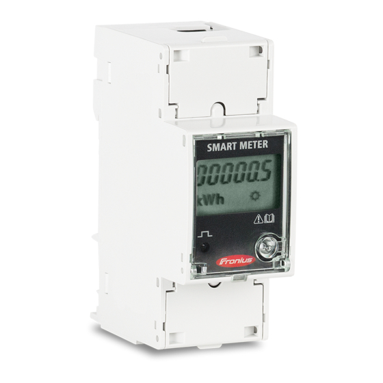
Fronius Smart Meter 63A-1
42,0426,0294,EN 007-04032021
Fronius prints on elemental chlorine free paper (ECF) sourced from certified sustainable forests (FSC).
Operating instructions
System monitoring
Advertisement
Table of Contents

Subscribe to Our Youtube Channel
Related Manuals for Fronius 63A-1


Summary of Contents for Fronius 63A-1
- Page 1 / Perfect Charging / Perfect Welding / Solar Energy LEARN MORE WITH OUR HOW-TO VIDEOS www.youtube.com/FroniusSolar Operating instructions Fronius Smart Meter 63A-1 System monitoring 42,0426,0294,EN 007-04032021 Fronius prints on elemental chlorine free paper (ECF) sourced from certified sustainable forests (FSC).
-
Page 3: Table Of Contents
Setting the address of the Fronius Smart Meter Start-up Fronius SnapINverter General Connecting to the Fronius Datamanager Configuring the Fronius Smart Meter as the primary meter Configuring the Fronius Smart Meter as a secondary meter Fronius GEN24 inverter General Installation using the web browser... -
Page 4: Safety Rules
Safety rules Explanation of DANGER! safety notices Indicates immediate danger. ▶ If not avoided, death or serious injury will result. WARNING! Indicates a potentially hazardous situation. ▶ If not avoided, death or serious injury may result. CAUTION! Indicates a situation where damage or injury could occur. ▶... -
Page 5: Environmental Conditions
For the location of the safety and danger notices on the device, refer to the section headed "General remarks" in the Operating Instructions for the device. Any equipment malfunctions which might impair safety must be remedied before the device is turned on. This is for your personal safety! Environmental Operation or storage of the device outside the stipulated area will be deemed as not in... -
Page 6: General
Failure to comply with this EU Directive may result in a negative impact on the environment and your health! Positioning The Fronius Smart Meter can be installed at two possible locations in the system: at the feed-in point and at the consumption point. - Page 7 Placement at the feed-in point Fronius Smart Meter located at the feed-in point. Placement at the consumption point Fronius Smart Meter located at the consumption load.
-
Page 8: Installation
Start-up on page 19). Mounting The Fronius Smart Meter can be mounted on a 35 mm DIN rail. The housing comprises 2 modules according to DIN 43880 Protective circuit The Fronius Smart Meter is a hard-wired device and requires a disconnecting device (cir- cuit breaker, switch or disconnector) and overcurrent protection (automatic circuit breaker). -
Page 9: Cabling
Connect each voltage cable to the terminal strip as shown in the graphic below. Connecting the Fronius SnapINverter: data communica- Connect the data communication connections of the Fronius Smart Meter to the Fronius tion cable to the system monitoring in the inverter. Several Smart Meters can be installed in the system, inverter... - Page 10 Connect 33 to D+. Fronius GEN24 inverter: Connect the data communication connections of the Fronius Smart Meter to the Modbus interface of the Fronius GEN24 inverter. Several Smart Meters can be installed in the system, see chapter Multi-meter system - Fronius GEN24 inverter on page 16.
-
Page 11: Terminating Resistors - Explanation Of Symbols
Meter - Fronius Smart Meter Terminating resistor R 120 Ohm is included in the scope of supply. Modbus RTU slave e. g. Fronius Ohmpilot, Fronius Solar Battery, etc. Terminating resistor R 120 Ohm Terminating res- Due to interference, it is recommended that terminating resistors are used as illustrated istors below to ensure proper functioning. -
Page 12: Multi-Meter System - Explanation Of Symbols
* The terminating resistor on Fronius Smart Meters is installed between 33 and 34. The terminating resistor R 120 Ohm is included with the Fronius Smart Meter. Multi-meter sys- Grid tem - Explanation supplies the loads in the system if insufficient power is being generated of symbols by the PV modules or supplied by the battery. -
Page 13: Modbus Participants - Fronius Snapinverter
Primary meter Records the system's load curve and provides measurement data for energy profiling in Fronius Solar.web. The primary meter also controls the dynamic feed-in control. Secondary meter Records the load curve of individual loads (e.g. washing machine, lamps, TV, heat pump, etc.) in the consumption branch and provides measurement data for energy profiling in Fronius Solar.web. -
Page 14: Multi-Meter System - Fronius Snapinverter
Secondary Ohmpilot meter meter Multi-meter sys- If several Fronius Smart Meters are installed, a separate address must be set for each tem - Fronius one (see Setting the address of the Fronius Smart Meter on page 17). The primary SnapINverter meter is always assigned address 1. -
Page 15: Modbus Participants - Fronius Gen24
Terminating resistors must be positioned individually for each channel. Modbus parti- The inputs M0 and M1 can be selected for this purpose. A maximum of 4 Modbus parti- cipants - Fronius cipants can be connected to the Modbus terminal on inputs M0 and M1. GEN24 IMPORTANT! Only one primary meter, one battery and one Ohmpilot can be connected per inverter. -
Page 16: Multi-Meter System - Fronius Gen24 Inverter
Secondary Ohmpilot meter meter Multi-meter sys- If several Fronius Smart Meters are installed, a separate address must be set for each tem - Fronius one (see Setting the address of the Fronius Smart Meter on page 17). The primary GEN24 inverter meter is always assigned address 1. -
Page 17: Menu Structure
Setting the Symbol Name Event Function address of the Prog Increases the set value Fronius Smart Meter Prog Proceeds to the next menu item 2 seconds Press "Prog" for 2 seconds to call up code entry. Enter the password "2633". Increase... - Page 18 Press "Prog" for 2 seconds to change to the menu item "Ad" (address). Set the relevant address. Permissible values: 1 - 14 IMPORTANT! Skip all other settings and leave them unchanged.
-
Page 19: Start-Up
Start-up... -
Page 21: Fronius Snapinverter
The service password must be entered in order to access the "Meter" menu item. Three-phase or single-phase Fronius Smart Meters can be used. In both cases, the selection is made under the "Fronius Smart Meter" item. The Fronius Datamanager auto- matically identifies the meter type. -
Page 22: Configuring The Fronius Smart Meter As A Secondary Meter
The Fronius Smart Meter is configured as a primary meter. The "Current general view" menu area displays the power of the PV modules, self-con- sumption, the energy fed into the grid and the battery charge (if available). Configuring the Go to the Fronius Datamanager website. -
Page 23: Fronius Gen24 Inverter
The technician password must be entered in order to access the "Device configuration" menu item. Three-phase or single-phase Fronius Smart Meters can be used. In both cases, the selection is made under the "Components" menu area. The meter type is determined automatically. -
Page 24: Configuring The Fronius Smart Meter As The Primary Meter
Access the "Components" menu area. Click the "Add component" button. In the "Position" drop-down list, set the position of the meter (feed-in point or con- sumption point). For more information on the position of the Fronius Smart Meter, Positioning on page 6. -
Page 25: Technical Data
Technical data Technical data Modbus transmission speed: 9600 baud Parity bit: None Software version: Datamanager 3.7.2 / Energypackage 1.3.3 Input Nominal voltage (1-phase) 230 V Operating range ±10% Self-consumption - voltage path (max. 4 VA (1.9 W) for 264 V voltage) Nominal frequency 50 - 60 Hz... -
Page 26: Fronius Manufacturer's Warranty
Wire (rigid) Min. 0.05 mm² / max. 4 mm² Wire (flexible) Min. 0.05 mm² / max. 2.5 mm² Recommended torque 0.5 Nm / max. 0.8 Nm Fronius manufac- Detailed, country-specific warranty terms are available on the internet: turer's warranty www.fronius.com/solar/warranty... - Page 27 To obtain the full warranty period for your newly installed Fronius inverter or storage sys- tem, please register at: www.solarweb.com.
- Page 28 FRONIUS INTERNATIONAL GMBH Froniusstraße 1 A-4643 Pettenbach AUSTRIA contact@fronius.com www.fronius.com Under www.fronius.com/contact you will find the addresses of all Fronius Sales & Service Partners and locations...
Need help?
Do you have a question about the 63A-1 and is the answer not in the manual?
Questions and answers