Fronius Smart Meter TS 65A-3 Operating Instructions Manual
Hide thumbs
Also See for Smart Meter TS 65A-3:
- Quick start manual (2 pages) ,
- Operating instructions manual (40 pages) ,
- Quick start manual (2 pages)

Related Manuals for Fronius Smart Meter TS 65A-3


Summary of Contents for Fronius Smart Meter TS 65A-3
- Page 1 Operating Instructions Fronius Smart Meter TS 65A-3 Operating Instructions 42,0426,0349,EN 015-20092023...
-
Page 3: Table Of Contents
Error messages Start-up Fronius SnapINverter General Connecting to the Fronius Datamanager Configuring the Fronius Smart Meter TS as the primary meter Configuring the Fronius Smart Meter TS as a secondary meter Fronius GEN24 inverter General Installation mit dem Browser Configuring the Fronius Smart Meter TS as the primary meter... -
Page 5: Safety Rules
Safety rules... -
Page 7: Safety Rules
Safety rules Explanation of DANGER! safety notices Indicates immediate danger. ▶ If not avoided, death or serious injury will result. WARNING! Indicates a potentially hazardous situation. ▶ If not avoided, death or serious injury may result. CAUTION! Indicates a situation where damage or injury could occur. ▶... -
Page 8: Environmental Conditions
Any safety devices that are not fully functional must be repaired by an author- ised specialist before the device is switched on. Never bypass or disable protection devices. For the location of the safety and danger notices on the device, refer to the sec- tion headed "General remarks"... -
Page 9: General Information
General information... -
Page 11: Fronius Smart Meter
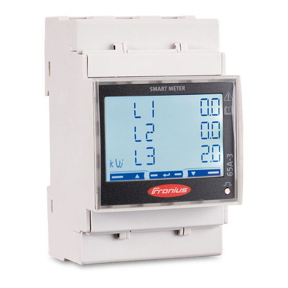
Fronius Smart Meter TS 65A-3 Device descrip- The Fronius Smart Meter TS is a bidirectional electricity meter which optimises tion self-consumption and records the household's load curve. In conjunction with the Fronius inverter, Fronius Datamanager and Fronius data interface, the Froni- us Smart Meter TS provides a clear overview of a user's own power consumption. -
Page 12: Information On The Device
Dangerous electrical voltage. Intended use The Fronius Smart Meter TS is a fixed piece of equipment for public grids of TN/TT systems and records self-consumption and/or individual loads in the sys- tem. The Fronius Smart Meter TS is required for systems with a battery storage... -
Page 13: Scope Of Supply
The manufacturer shall not be liable for any damage resulting from such use. Reasonably foreseeable misuse: The Fronius Smart Meter TS is not suitable for the supply of life-sustaining med- ical devices or for the billing of subtenants. Scope of supply... - Page 14 Positioning at the feed-in point: Positioning at consumption point:...
-
Page 15: Installation
Installation... -
Page 17: Installation
The update can be started via the in- verter web page or using Solar.web. If several Fronius Smart Meter TS are installed in the system, set the address (see "Setting the address" under "Setting the address on the Fronius Smart... -
Page 18: Cabling
The Fronius Smart Meter TS consumes 10 - 30 mA, the nominal capacity of the disconnecting devices and the overcurrent‑protection is determined by the wire thickness, the mains voltage and the required breaking capacity. Disconnecting devices must be mounted within sight and as close as possible to the Fronius Smart Meter TS;... -
Page 19: Fitting The Protective Cover For The Terminals
Connecting the Connect the data communication connections of the Fronius Smart Meter TS to data communic- the Modbus interface of the Fronius inverter using a network cable (type CAT5 ation cable to or higher). the inverter... -
Page 20: Terminating Resistors - Explanation Of Symbols
Two wires can be installed in each terminal; the wires are twisted first, inser- ted into the terminal and tightened. Note: A loose wire can disable an entire area of the network. The data communication connections of the Fronius Smart Meter TS are electrically isolated from hazardous voltages. Terminating res-... -
Page 21: Connecting The Terminating Resistor
Connecting the The terminating resistor is integrated terminating res- in the Fronius Smart Meter TS and is istor manufactured with a bridge between the M and T connections (T = termina- tion). Terminating res- Due to interference, it is recommended that terminating resistors are used as il- istors lustrated below to ensure proper functioning. -
Page 22: Mounting The Connection Cover
* The terminating resistor is integrated in the Fronius Smart Meter TS and is manufactured with a bridge between the M and T connections (T = termination). Mounting the Insert the connection covers into the connection cover guides and press firmly. -
Page 23: Multi-Meter System - Explanation Of Symbols
Primary meter Records the system's load curve and provides measurement data for energy profiling in Fronius Solar.web. The primary meter also controls the dynamic feed-in control. Secondary meter Records the load curve of individual loads (e.g. washing machine, lamps, TV, heat pump, etc.) in the consumption branch and... -
Page 24: Modbus Participants - Fronius Snapinverter
Battery Ohmpilot Primary meter Secondary meter Multi-meter sys- If several Fronius Smart Meter TS are installed, a separate address must be set tem - Fronius for each (see Setting the address on the Fronius Smart Meter TS on page 31). -
Page 25: Modbus Participants - Fronius Gen24
Terminating resistors must be positioned individually for each channel. Modbus parti- The inputs M0 and M1 can be selected for this purpose. A maximum of 4 Modbus cipants - Fronius participants can be connected to the Modbus terminal on inputs M0 and M1. GEN24... -
Page 26: Multi-Meter System - Fronius Gen24 Inverter
Battery Ohmpilot Primary meter Secondary meter Multi-meter sys- If several Fronius Smart Meter TS are installed, a separate address must be set tem - Fronius for each (see Setting the address on the Fronius Smart Meter TS on page 31). -
Page 27: Menu - Measured Variables
The following must be observed in a multi-meter system: Connect the primary meter and the battery to different channels (recom- mended). The remaining Modbus participants must be distributed equally. Only assign each Modbus address once. Terminating resistors must be positioned individually for each channel. Menu - Measured Scree variables... - Page 28 Scree Image Description Total active energy drawn* Total reactive power Total reactive energy supplied** Total reactive power Total active energy drawn** Total apparent power Total active energy drawn* Maximum demanded power (P = Peak de- mand) that has been reached since the last reset.
- Page 29 Scree Image Description Apparent power Reactive energy drawn Power factor (L = inductive, C = capacit- ive) Phase voltage Conductor voltage Current Effective power Displayed when easy connection mode is activated (measurement = A). This value indicates the total energy without considering the direction. Factory setting - displayed when drawn and delivered energy are meas- ured separately (measurement = b).
-
Page 30: Configuration Menu - Structure And Parameters
Configuration Screen Code Description Values menu - structure PASS*** Enter the current password 2633* and parameters nPASS Password change ** Four digits (0000-9999) SYStEM Type of system 3Pn*: three-phase system, 4-core 3P: three-phase system, 3- core 2P: two-phase system, 3- core MEASurE Measurement mode **... -
Page 31: Setting The Address On The Fronius Smart Meter Ts
Setting the ad- Symbol Name Event Function dress on the Scroll one screen forward, increase the Fronius Smart value by 1 Meter TS Down Scroll one screen back, decrease the value by 1 Enter Call up settings, confirm value 2 seconds Press and hold "Enter"... -
Page 33: Start-Up
Start-up... -
Page 35: Fronius Snapinverter
The service password must be entered in order to access the "Meter" menu item. Three-phase or single-phase Fronius Smart Meter TS can be used. In both cases, the selection is made under the "Fronius Smart Meter" item. The Fronius Datamanager automatically identifies the meter type. -
Page 36: Configuring The Fronius Smart Meter Ts As A Secondary Meter
Click the button to save the settings. The Fronius Smart Meter TS is configured as a primary meter. "Current general view" menu area displays the power of the PV modules, self-consumption, the energy fed into the grid and the battery charge (if avail- able). -
Page 37: Fronius Gen24 Inverter
"Device configura- tion" menu item. Three-phase or single-phase Fronius Smart Meter TS can be used. In both cases, the selection is made under the "Components" menu area. The meter type is de- termined automatically. A primary meter and several secondary meters can be selected. The primary meter needs to be configured first before a secondary meter can be selected. -
Page 38: Configuring The Fronius Smart Meter Ts As The Primary Meter
Click the "Add component" button. In the "Position" drop-down list, set the position of the meter (feed-in point or consumption point). For more information on the position of the Fronius Smart Meter TS, see Positioning on page 13. Click the "Add"... - Page 39 Enter the name of the meter in the input field. In the "Category" drop-down list, select the category (producer or load). Click the "Add" button. Click the "Save" button to save the settings. The Fronius Smart Meter TS is configured as a secondary meter.
-
Page 40: Technical Data
Technical data Technische Modbus Übertragungsgeschwindigkeit: 9600 baud Daten Paritätsbit: keines Softwareversion: Fronius Datamanager 2.0 (ab Version 3.16.1) Fronius Symo Hybrid (ab Version 1.16.1) Messeingang Nennspannung 208 - 400 V Arbeitsbereich 166,4 - 480 V Leistungsaufnahme im Spannungsp- ≤ 10 VA fad (max. - Page 41 Isolation (EN IEC 62052-11, EN IEC 62053-21) Isolationsspannung 4 kVAC RMS (1min) Elektromagnetische Verträglichkeit Emissionstest gem. EN IEC 62052-11, EN 50470-3 Immunitätstest gem. EN IEC 62052-11, EN 50470-3 Arbeitsbedingungen Referenztemperatur 25° C (±5° C) Arbeitsbereich -25 bis +55° C Grenztemperatur für Lagerung und -30 bis +80°...
-
Page 42: Fronius Manufacturer's Warranty
Anschlussklemmen Empfohlenes Drehmoment max. 0,4 Nm Fronius manu- Detailed, country-specific warranty terms are available on the internet: facturer's war- www.fronius.com/solar/warranty ranty To obtain the full warranty period for your newly installed Fronius inverter or storage system, please register at: www.solarweb.com.
Need help?
Do you have a question about the Smart Meter TS 65A-3 and is the answer not in the manual?
Questions and answers