Fronius 63A-1 Quick Manual
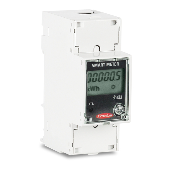
Smart meter
Hide thumbs
Also See for 63A-1:
- Operating instructions manual (32 pages) ,
- Quick manual (20 pages) ,
- Quick start manual (10 pages)
Advertisement
Quick Links
HOW TO INSTALL A FRONIUS SMART
METER 63A-1 AND 63A-3
*for 63A-1, 63A-3 whole current Fronius Smart Meters only. For the 50kA
Fronius Smart Meter and 240V/480V UL Fronius Smart Meters please refer to
their respective guides.
Quick Guide
© Fronius Australia Pty Ltd.,
Version 3.0/2019
Fronius reserves all rights, in particular rights of reproduction, distribution and translation.
No part of this work may be reproduced in any way without the written consent of Fronius. It must not be saved, edited,
reproduced or distributed using any electrical or electronic system.
You are hereby reminded that the information published in this document, despite exercising the greatest of care in its
preparation, is subject to change and that neither the author nor Fronius can accept any legal liability
Gender-specific wording refers equally to female and male form.
1/17
(c) Fronius Australia Pty. Ltd, 01/2019
Advertisement

Related Manuals for Fronius 63A-1


Summary of Contents for Fronius 63A-1
- Page 1 Fronius reserves all rights, in particular rights of reproduction, distribution and translation. No part of this work may be reproduced in any way without the written consent of Fronius. It must not be saved, edited, reproduced or distributed using any electrical or electronic system.
- Page 2 Eco SnapINverters, excluding Light versions. It can also be retrofitted to all other Fronius inverters). This document describes how to install and set up only the 63A-1 single phase or 63A-3 3-phase Fronius Smart Meters. Please use the below links if using a different model of Fronius Smart Meter.
- Page 3 With the Fronius Smart Meter there are two possible energy paths/ locations where it can be installed. In almost all cases, the Fronius Smart Meter will be installed in the feed-in path. This is also the default setting in the Datamanager’s METER section.
- Page 4 Connection is a data line for Modbus RTU / RS485 using screw terminals on the meter. Maximum distance: 300 m (980 feet) Use a single core per terminal connection between Fronius Smart Meter and Datamanager 2.0. For D+ and D- use the single cores from the same colour (e.g. D+ is orange/white, D- is orange) Meter connection on the Datamanager 2.0...
- Page 5 2.1.1 - Wiring detail for single-phase Fronius Smart Meter 63A/1PH & Datamanager 2.0 2.1.2 - Wiring detail for three-phase Fronius Smart Meter 63A/3PH and Datamanager 2.0 Modbus termination switch on the Datamanager The internal bus termination 120-Ohm resistance (for Modbus RTU) needs to be switched to ON.
- Page 6 It is recommended to complete the Solar.web Wizard first and get the system online. Once completed please go to Section 2.2.1 for the Fronius Smart Meter activation. If the system is not being set up for online monitoring, the Fronius Smart Meter can be activated within the Technician Wizard as per Section 2.2.2.
- Page 7 Step 2 Select PASSWORDS Step 3 Set a service password. Step 4 Minimum 8 characters with Select the tick to save numbers and letters the new password Step 5 Select METER tab Step 6 Login with Username: service and the password from Step 3 7/17 02/2017...
- Page 8 Step 7 Select Fronius Smart Meter from the drop down menu Step 8 Select the Settings button Step 9 Leave this window open until the State changes to OK or Timeout If the State is Timeout then retry Step 10 the process.
- Page 9 Connect your computer/table/smart phone to the Fronius_240.XXXXXX network Open a web browser and go to http://192.168.250.181. Alternatively you can use the Fronius SolarWeb App (Tablet/Smart Phone), open the Solar.web app and select Settings. Then select PV Inverter Homepage or Your System Monitoring depending on your device.
- Page 10 Step 1 Select Technician Wizard to begin Step 2 Set System Name, Yield and Date/Time then select Forward 10/17 02/2017...
- Page 11 Step 3 Set the DC array Watt Peak (Wp) value for all inverters then select Forward Important: Make a note of the service password as it’s required to make any changes to the smart meter settings later on Step 4 Set a service password to limit access.
- Page 12 Step 5 Login with username: service and the password created in Step 4 Step 6 Skip Forward over IO Mapping 12/17 02/2017...
- Page 13 Step 7 Select Fronius Smart Meter from the dropdown box and then select Settings Older software versions do not have the List of Configured Meters or Secondary Meter Step 8 Leave this window open until the State changes to OK or...
- Page 14 Step 9 If State is OK then set meter location and select OK. Refer to Section 1.1 of this guide for If the State is Timeout then retry explanation of locations the process. If it still times-out refer to troubleshooting steps in Section 4 of this guide Older software versions do not have the List of Configured...
- Page 15 If an export limit needs to be set, please refer to our Step 11 separate export limiting guide. Select Forward The Technician Wizard is now complete and the meter has been setup. Online monitoring can be setup via the Solar.Web Wizard 15/17 02/2017...
- Page 16 1) Enter the Setup menu 2) Scroll down and enter Display Settings 3) Scroll down and enter Night Mode 4) Set to ON and enter to save the setting *Night mode: Not applicable on Fronius Symo Hybrid inverters. 16/17 02/2017...
- Page 17 4. FRONIUS SMART METER TROUBLESHOOTING 4.1 – Timeout: meter not detected If the Fronius Smart Meter is not being detected in the Technician wizard or PV Inverter homepage try the following steps in order. After each step try to activate the meter again.
Need help?
Do you have a question about the 63A-1 and is the answer not in the manual?
Questions and answers