
Related Manuals for Fronius WR


Summary of Contents for Fronius WR
- Page 1 Operating Instructions Fronius Smart Meter WR EN-US Operating instructions 42,0426,0455,EA 002-31082022...
-
Page 3: Table Of Contents
Circuit Protection Line Wiring Connect Current Transformers CT Wiring Connecting data communication cables to inverters Set the address of the Fronius Smart Meter Terminating resistors - explanation of symbols Terminating Resistors Set Baud Rate Multi meter system - Explanation of symbols... -
Page 4: Safety Rules
Safety rules Explanation of DANGER! Safety Instruc- tions Indicates an immediate danger. ▶ Death or serious injury may result if appropriate precautions are not taken. WARNING! Indicates a possibly dangerous situation. ▶ Death or serious injury may result if appropriate precautions are not taken. CAUTION! Indicates a situation where damage or injury could occur. -
Page 5: Environmental Conditions
Copyright Copyright of these Operating Instructions remains with the manufacturer. Text and illustrations were accurate at the time of printing. Fronius reserves the right to make changes. The contents of the Operating Instructions shall not provide the basis for any claims whatsoever on the part of the purchaser. If you... -
Page 6: Disposal
cordance with Part 15 of the FCC regulations. The limit values should provide adequate protection against harmful interference in homes. This device creates and uses high frequency energy and can interfere with radio communications when not used in accordance with the instructions. However, there is no guaran- tee against interference occurring in a particular installation. -
Page 7: General
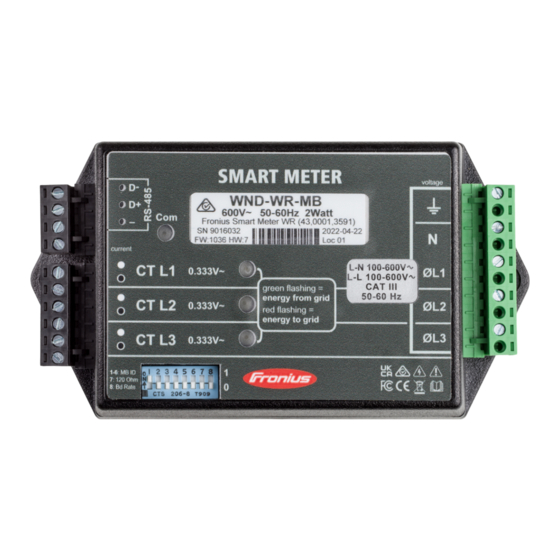
Together with the Fronius inverter, the Fronius Datamanager and the Fronius data inter- face, the Fronius Smart Meter provides a clear overview of your own power con- sumption. The meter measures the power flow to the loads or to the grid and forwards the information to the Fronius inverter via ModBus RTU/RS485 communication. - Page 8 Positioning at the consumption point The positioning of the Fronius Smart Meter at the consumption point.
-
Page 9: Installation
23). Mounting The Fronius Smart meter has two mounting holes spaced 5.4 in. (137 mm) apart (center-to-center). These mounting holes are normally obscured by the detach- able screw terminals. Remove the screw terminals to mark the hole positions and mount the meter. -
Page 10: Circuit Protection
(circuit breaker, switch or disconnect) and overcur- rent protection (fuse or circuit breaker). The Fronius Smart Meter only draws 10-30 mA, so the rating of any switches, dis- connects, fuses and / or circuit breakers is determined by the wire gauge, the mains voltage and the current interrupting rating required. - Page 11 240 Vac (US) e.g. 240 Vac (US) / e.g. 120 Vac (US) / 400 / 480 Vac (US) 240 Vac (US) Single-Phase Two-Wire without Neutral Single-Phase Two-Wire with Neutral Fronius Smart Meter Fronius Ground Inverter CT L1 CT L2 Shorting...
- Page 12 Three-Phase Four-Wire Wye Three-Phase Three-Wire Delta without Neutral Three-Phase Four-Wire Stinger...
-
Page 13: Connect Current Transformers
Install the CTs around the conductor to be measured and connect the CT leads to the Fronius Smart Meter. Always turn off power before disconnecting any live conductors. Put the line conductors through the CTs as shown in the previous section. -
Page 14: Connecting Data Communication Cables To Inverters
Connecting data Fronius SnapINveter: communication Connect the data communication ports of the Fronius Smart Meter to the Froni- cables to invert- us system monitoring in the inverter. Several Smart Meters can be installed in the Multi meter system - Fronius SnapINverter... -
Page 15: Set The Address Of The Fronius Smart Meter
The outputs of the Fronius Smart Meter are galvanically isolated from dan- gerous voltages. Set the address The Fronius Smart Meter must be connected to the Fronius Datamanager. If only of the Fronius one Fronius Smart Meter is installed, the Modbus Address is 1. -
Page 16: Terminating Resistors - Explanation Of Symbols
Meter - Fronius Smart Meter Terminating resistor is integrated in the meter. Modbus RTU slave e.g. Fronius Ohmpilot, Fronius Solar Battery, etc. Termination resistance R 120 Ohm Terminating Res- The system might work without terminating resistors. Due to interferences, the... -
Page 18: Set Baud Rate
Secondary meter records the load curve of individual loads (e.g. washing machine, lights, television, heat pump, etc.) in the consumption branch and makes the measured data available for energy profiling in Fronius Solar.web. -
Page 19: Modbus Participant - Fronius Snapinverter
Ohmpilot meters meters Multi meter sys- If several Fronius Smart Meters are installed, a separate address must be set for tem - Fronius each one (see Set the address of the Fronius Smart Meter on page 15). The SnapINverter primary meter always receives the address 1. -
Page 20: Modbus Participant - Fronius Gen24
2 to 14. Different Fronius Smart Meter power categories can be used together. IMPORTANT! Use no more than 3 secondary meters in the system. To avoid interference, it is recommended to install the terminating resistors according to the chapter... -
Page 21: Multi Meter System - Fronius Gen24 Inverter
Ohmpilot meters meters Multi meter sys- If several Fronius Smart Meters are installed, a separate address must be set for tem - Fronius each one (see Set the address of the Fronius Smart Meter on page 15). The GEN24 inverter primary meter always receives the address 1. - Page 22 Position of the primary meter in the consumption branch. *Termination resistance R 120 Ohm Position of the primary meter at the feed-in point. *Termination resistance R 120 Ohm The following must be observed in a multi meter system: Connect the primary meter and the battery to different channels (recom- mended).
-
Page 23: Commissioning
Commissioning... -
Page 25: Fronius Snapinverter
The service password must be entered for the "Meter" menu item. Three-phase or one-phase Fronius Smart Meters may be used. In both cases, se- lection is made via the "Fronius Smart Meter" item. The Fronius Datamanager automatically detects the meter type. -
Page 26: Configure Fronius Smart Meter As A Secondary Meter
Click on the button to save the settings. The Fronius Smart Meter is configured as a primary meter. In the menu area "Current Total View", the power of the PV modules, the self- consumption, the grid power feed and battery charging (if available) are dis- played. -
Page 27: Fronius Gen24 Inverter
The service password must be entered for the "Device configuration" menu item. Three-phase or one-phase Fronius Smart Meters may be used. In both cases, se- lection is made via the "Components" menu area. The meter type is determined automatically. -
Page 28: Configure Fronius Smart Meter As Primary Meter
Call up the "Components" menu area. Click on the “Add components” button. Set the position of the meter (feed-in point or consumption point) in the "Po- sition" drop-down list. For more information on the position of the Fronius Smart Meter, see Positioning on page 7. - Page 29 The Fronius Smart Meter is configured as a secondary meter.
-
Page 30: Operation
Operation Power Status The three status LEDs on the front of the Fronius Smart Meter can help indicate LEDs correct measurements and operation. The “L1”, “L2”, and “L3” on the diagrams indicate the three phases: Normal Startup The Fronius Smart Meter displays the following startup sequence whenever power is first applied. -
Page 31: Modbus Communication Leds
plied to the meter. If the voltages are correct, call customer service for assist- ance. Error If the meter experiences an internal error, all LEDs will light up red for 3 or more seconds. If you see this happen repeatedly, call customer service for assistance. Modbus Commu- Near the upper left corner, there is a diagnostic Com (communication) LED that nication LEDs... -
Page 32: Technical Data
The Fronius Smart Meter has an optional neutral connection that may be used for measuring wye circuits. In the absence of neutral, voltages are measured with respect to ground. The Fronius Smart Meter uses the phase L1 (øA) and phase L2 (øB) connections for power. -
Page 33: Certifications
Power Consumption: Operating Frequencies: 50 / 60 Hz Measurement Category: CAT III Measurement category III is for measurements performed in the building install- ation. Examples are measurements on distribution boards, circuit breakers, wir- ing, including cables, bus bars, junction boxes, switches, socket outlets in the fixed installation, and equipment for industrial use and some other equipment, for example, stationary motors with permanent connection to the fixed installa- tion. -
Page 34: Environmental
(Hammond Mfg., Type EJ Series) rated NEMA 3R or 4 (IP 66). Fronius manu- Detailed warranty conditions specific to your country can be found online: facturer's war- www.fronius.com/solar/garantie ranty To take advantage of the full warranty duration for your newly installed Fronius inverter or storage system, register your product at: www.solarweb.com.
Need help?
Do you have a question about the WR and is the answer not in the manual?
Questions and answers