Fronius Smart Meter IP Operating Instructions Manual
Hide thumbs
Also See for Smart Meter IP:
- Quick start manual (4 pages) ,
- Operating instructions manual (56 pages)

Subscribe to Our Youtube Channel
Related Manuals for Fronius Smart Meter IP


Summary of Contents for Fronius Smart Meter IP
- Page 1 Operating Instructions Fronius Smart Meter IP Operating Instructions 42,0426,0464,EN 008-28052024...
-
Page 3: Table Of Contents
Setting the Modbus RTU terminating resistor Terminating resistors Setting the Modbus RTU BIAS Start-up Commissioning the Fronius Smart Meter IP Opening the user interface with the QR code Opening the user interface with the IP address Software update Fronius SnapINverter General Connecting to the Fronius Datamanager 2.0... - Page 4 Configuring the primary meter Configuring secondary meters Modbus participants - Fronius GEN24 Multi-meter system - Explanation of symbols Multi-meter system - Fronius GEN24 inverter User interface Overview Overview Settings Advanced settings Restoring the factory settings Changing the input current of the current transformers...
-
Page 5: Safety Rules
Safety rules... -
Page 7: Safety Rules
Safety rules Explanation of DANGER! safety notices Indicates immediate danger. ▶ If not avoided, death or serious injury will result. WARNING! Indicates a potentially hazardous situation. ▶ If not avoided, death or serious injury may result. CAUTION! Indicates a situation where damage or injury could occur. ▶... -
Page 8: Environmental Conditions
Any safety devices that are not fully functional must be repaired by an author- ised specialist before the device is switched on. Never bypass or disable protection devices. For the location of the safety and danger notices on the device, refer to the sec- tion headed "General remarks"... -
Page 9: General Information
General information... -
Page 11: Fronius Smart Meter Ip
New Zealand. Intended use The Fronius Smart Meter IP is a fixed piece of equipment for public grids of TN/TT systems and may only be used to measure loads and self-consumption. The Fronius Smart Meter IP is required for systems with a battery storage system and/or a Fronius Ohmpilot installed for communication between the individual components. -
Page 12: Scope Of Supply
The available documentation forms part of the product and must be read, ob- served and kept in good condition. It must also be accessible at all times at the place of installation. Fronius International GmbH assumes no responsibility for compliance with or non-compliance with these laws or regulations in connection with the installation of the product. -
Page 13: Measuring Accuracy
Positioning at the consumption point Measuring ac- The Fronius Smart Meter IP has accuracy class 1 when measuring active energy curacy (EN IEC 62053-21) in the voltage ranges 208 - 480 VLL and 100 - 240 VLN. For Technical data on page 54. -
Page 14: Control Elements, Connections And Displays
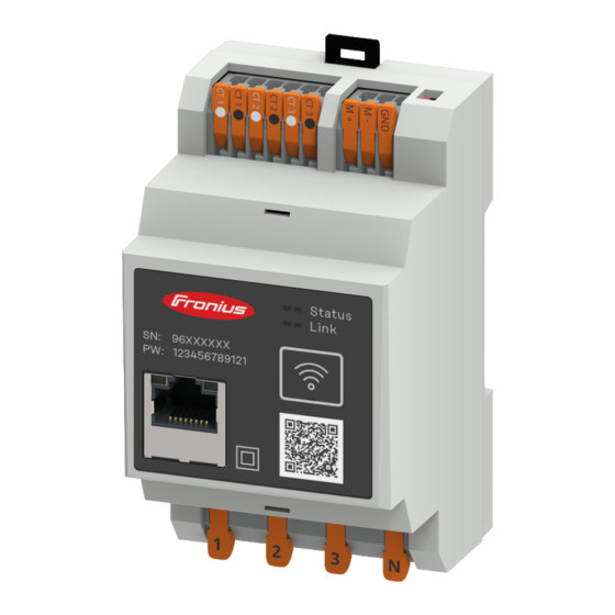
QR code to start the Setup wiz- AC connection area LED status indic- The LED status indicators show the operating status and data connection of the ators Fronius Smart Meter IP. Status 1 LED Lights up green: Ready for operation Status 2 LED... -
Page 15: Installation
Installation... -
Page 17: Preparations
Preparations Choice of loca- Please note the following criteria when choosing a location for the Smart Meter: tion Only install on a solid, non-flammable surface. When installing the Smart Meter in a switch cabinet or similar enclosure, make sure that it is of the appropriate safety class and that the hot air that develops will be dissipated by forced-air ventilation. -
Page 18: Installation
(see Connecting the current transformers on page 22). Establish the data connection of the Fronius Smart Meter IP. The data con- nection can be established in three different ways: Modbus RTU (recommended for backup power operation), see page 23. -
Page 19: Installation
(automatic circuit breaker). The Fronius Smart Meter IP consumes 30 mA, the nominal capacity of the dis- connecting devices and the overcurrent protection is determined by the conduct- or cross-sections, the mains voltage and the required breaking capacity. -
Page 20: Cabling
Cabling WARNING! Danger from live mains voltage inputs An electric shock can be fatal. ▶ Switch off the power supply be- fore connecting the mains voltage inputs. Permissible conductor cross-section of AC terminals: Wire: 1.5 - 4 mm² Each live conductor must be connected to the AC terminals as shown in the fig- ures below. -
Page 21: Suitable Current Transformers
It is recommended to use Fronius CT current transformers (item numbers transformers 41,0010,0104 / 41,0010,0105 / 41,0010,0232). To ensure smooth operation of the Fronius Smart Meter IP and accurate measurement results, all connected current transformers must meet these requirements: The current transformer must generate 333 mV at nominal current. The nominal current of the current transformers is listed in the data sheet for the current transformer. -
Page 22: Connecting The Current Transformers
Note down the nominal current of the current transformer for each meter. These values will be required for commissioning. Attach the current transformers to the conductor to be measured and con- nect the current transformer cables to the Fronius Smart Meter IP. WARNING! Danger from mains voltage An electric shock can be fatal. -
Page 23: Connecting The Lan
Modbus interface of the Fronius inverter using a CAT 5 STP (Shielded Twis- ted Pair) or higher data cable. The Fronius Smart Meter IP can also be connected to the network (LAN / WLAN). This allows software updates to be carried out. -
Page 24: Terminating Resistors - Explanation Of Symbols
IMPORTANT! A loose wire can disable an entire area of the network. The data communication connections of the Fronius Smart Meter IP are electrically isolated from hazard- ous voltages. Further information for commissioning Observe the following information on connecting the data communication cable to the inverter. -
Page 25: Setting The Modbus Rtu Terminating Resistor
R 120 Ohm Setting the Mod- The terminating resistor is integrated bus RTU termin- in the Fronius Smart Meter IP and is ating resistor set by a switch. For information on whether the ter- minating resistor must be set or not,... -
Page 26: Setting The Modbus Rtu Bias
OPTION 2 1 = ON 0 = OFF Manufacturer manual Manufacturer manual Third party device / Modbus RTU max. 300 m OPTION 3 1 = ON 0 = OFF Manufacturer manual Manufacturer manual e.g. Ohmpilot, Battery max. 300 m OPTION 4 1 = ON 0 = OFF Manufacturer manual... - Page 27 Battery Battery...
-
Page 29: Start-Up
Start-up... -
Page 31: Commissioning The Fronius Smart Meter Ip
Enter the initial password and press Login. Follow the instructions in the installation wizard and complete the installa- tion. Add the Smart Meter IP on the user interface of the inverter (see Commis- sioning GEN24 / SnapINverter). Opening the user... -
Page 32: Software Update
If this function is not activated, software updates can also be searched for and started manually on the user interface of the device. The software of the Fronius Smart Meter IP is compatible with the following soft- ware versions of connected Fronius components: Fronius GEN24 &... -
Page 33: Fronius Snapinverter
A primary meter and several secondary meters can be selected. The primary meter needs to be configured first before a secondary meter can be selected. The Fronius Smart Meter IP can be connected with Modbus TCP or Modbus RTU. Connecting to... -
Page 34: Configuring Secondary Meters
Settings button. If using Fronius Smart Meter (TCP), enter the IP address of the Fronius Smart Meter IP. A static IP address is recommended for the Fronius Smart Meter. Set the position of the meter (feed-in point consumption point). For more... -
Page 35: Multi-Meter System - Explanation Of Symbols
Primary meter Records the system's load curve and provides measurement data for energy profiling in Fronius Solar.web. The primary meter also controls the dynamic feed-in control. Secondary meter Records the load curve of individual loads (e.g. washing machine, lamps, TV, heat pump, etc.) in the consumption branch and... -
Page 36: Multi-Meter System - Fronius Snapinverter
Terminating resistor R 120 Ohm Multi-meter sys- If several Fronius Smart Meters are installed, a separate address must be set for tem - Fronius each one (see Advanced settings on page 48). The primary meter is always as- SnapINverter signed address 1. - Page 37 Location of the primary meter at the feed-in point. *Terminating resistor R 120 Ohm The following must be observed in a multi-meter system: Only assign each Modbus address once. Terminating resistors must be positioned individually for each channel.
-
Page 38: Fronius Gen24 Inverter
A primary meter and several secondary meters can be selected. The primary meter needs to be configured first before a secondary meter can be selected. The Fronius Smart Meter IP can be connected with Modbus TCP or Modbus RTU. Installation us-... -
Page 39: Configuring The Primary Meter
12. Smart Meter IP, see If using Fronius Smart Meter (TCP), enter the IP address of the Fronius Smart Meter IP. A static IP address is recommended for the Fronius Smart Meter. Click the button. Click the Save button to save the settings. -
Page 40: Modbus Participants - Fronius Gen24
Log into the Smart Meter IP user interface and change the Modbus address accordingly under Advanced settings > Data interface > Modbus address = primary meter) This setting is necessary when using Modbus TCP and RTU. Call up the user interface of the inverter. -
Page 41: Multi-Meter System - Explanation Of Symbols
Primary meter Records the system's load curve and provides measurement data for energy profiling in Fronius Solar.web. The primary meter also controls the dynamic feed-in control. Secondary meter Records the load curve of individual loads (e.g. washing machine, lamps, TV, heat pump, etc.) in the consumption branch and... -
Page 42: Multi-Meter System - Fronius Gen24 Inverter
Terminating resistor R 120 Ohm Multi-meter sys- If several Fronius Smart Meters are installed, a separate address must be set for tem - Fronius Advanced settings on page 48). The primary meter is always as- each one (see GEN24 inverter signed address 1. - Page 43 Location of the primary meter at the feed-in point. *Terminating resistor R 120 Ohm The following must be observed in a multi-meter system: Connect the primary meter and the battery to different channels (recom- mended). The remaining Modbus participants must be distributed evenly. Only assign each Modbus address once.
-
Page 45: User Interface
User interface... -
Page 47: Overview
For more information on the settings, see chapter Advanced settings on page 48. Info Various information about the Fronius Smart Meter IP is displayed here. This information can be helpful in support cases. Logout The current user is logged out. -
Page 48: Settings
Modbus TCP Port: This value must match the setting on the inverter (standard port: 502). Single-phase/multiphase The connection type of the Fronius Smart Meter IP can be selected here. Restart device Click on Restart device to restart the Fronius Smart Meter IP. -
Page 49: Restoring The Factory Settings
Press and hold the WLAN access point factory settings and reset button for 20 seconds to re- set the Fronius Smart Meter IP to factory settings. All LEDs on the Fronius Smart Meter IP go out and the device re- starts (can take max. -
Page 51: Appendix
Appendix... -
Page 53: Care, Maintenance And Disposal
Observe locally valid regulations Compress the cardboard box to reduce volume Fronius manu- Detailed, country-specific warranty conditions are available at www.fronius.com/ facturer's war- solar/warranty. ranty To obtain the full warranty period for your newly installed Fronius product, please register at www.solarweb.com. -
Page 54: Technical Data
Technical data Technical data Measuring input Nominal voltage (3-phase) including 208 - 480 V tolerance Nominal voltage (1-phase) including 100 - 240 V tolerance Self-consumption 30 mA Nominal frequency 50 - 60 Hz Tolerance 47 - 63 Hz Maximum current, I 5000 A Short-time overload 3x I... - Page 55 Output Baud rate (Modbus transmission 9600 bit/s speed) Response time ≤ 200 ms WLAN Frequency range 2412 - 2472 MHz Channels used Channel: 1-13 b,g,n HT20 Channel: 3-9 HT40 Output <18 dBm Modulation 802.11b: DSSS (1Mbps DBPSK, 2M- bps DQPSK, 5.5/11Mbps CCK) 802.11g: OFDM (6/9Mbps BPSK, 12/18Mbps QPSK, 24/36Mbps 16- QAM, 48/54Mbps 64-QAM)
- Page 56 Housing Connection Spring-loaded terminals Mounting 35 mm DIN rail Housing material PA-765 UL Protection class (EN 60529) IP20 housing, IP30 connections Weight 132 grams Terminals Voltage input Wire min. 1.5 mm² / max. 4 mm² Data output and current transformer input Wire min.
Need help?
Do you have a question about the Smart Meter IP and is the answer not in the manual?
Questions and answers