
Related Manuals for SMC Networks C96N C Series


Summary of Contents for SMC Networks C96N C Series
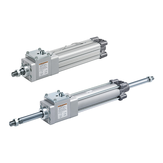
- Page 1 Doc. no.C96N-OM0198Q PRODUCT NAME Cylinder with lock MODEL / Series / Product Number C96N*32&100-*C...
-
Page 2: Table Of Contents
Contents Safety Instructions Product Specifications 1-1. Cylinder specifications 1-2. Lock unit specifications 1-3. Stop accuracy 1-4. Precautions on model selection Installation and Handing 2-1. Air supply 2-2. Design P.10 2-3. Mounting P.11 2-4. Operating environment P.12 2-5. Speed control P.13 2-6. -
Page 3: Safety Instructions
Safety Instructions These safety instructions are intended to prevent hazardous situations and/or equipment damage. These instructions indicate the level of potential hazard with the labels of “Caution,” “Warning” or “Danger.” They are all important notes for safety and must be followed in addition to International Standards (ISO/IEC) , and other safety regulations. - Page 4 Safety Instructions Caution The product is provided for use in manufacturing industries. The product herein described is basically provided for peaceful use in manufacturing industries. If considering using the product in other industries, consult SMC beforehand and exchange specifications or a contract if necessary. If anything is unclear, contact your nearest sales branch.
-
Page 5: Product Specifications
1. Product Specifications 1-1. Cylinder specification Bore size (mm) Action Double acting/single rod Fluid Proof pressure 1.5MPa Max. operating pressure 1.0MPa Min. operating pressure 0.08MPa Without auto switch:-10℃ to 70℃ Ambient and fluid (No freezing) temperatures With auto switch:-10℃ to 60℃ Lubricant Not required (Non-lube) 50 to 1,000mm/s *... -
Page 6: Precautions On Model Selection
1-4.Precautions on model selection C a u t i o n ①Choose the optimum bore size based on the applications operating conditions such as load, travel distance (stroke), stroke time, mounting orientation, operating pressure, etc. ②Attention should be taken so that the operating speed does not exceed the max. speed for the cylinder. Adjust the maximum speed of cylinder using the speed controller so that the load travels the stroke slower than the stroke time, ③Stroke time means the time taken for the load moving from the start of the stroke to the end without intermediate stop. - Page 7 Selection graph - 6 -...
- Page 8 Step 3 Make sure that the allowable kinetic energy of cylinder is not exceeded. Based on the Graph 8, confirm that the allowable kinetic energy of the cylinder is not exceeded at the load weight and maximum speed selected in Step 1 and 2. 1) Air cushion is effective 2) Air cushion is not utilized Graph 8.
- Page 9 Step 4 Lateral load applied to the rod end shall not exceed the limit of allowable load. Make sure that lateral load applied to the piston rod end does not exceed the allowable load limit referring to the Graph 9. Bushing (bearing) Chart 9 Allowable lateral load applied to rod end The bold solid lines in Chart 9 show the allowable lateral load on the cylinder for a certain stroke length.
-
Page 10: Installation And Handing
2. Installation and Handling 2-1. Air supply ① The air supplied to the cylinder should be filtered by SMC AF series air filter and regulated to the specified set pressure by SMC AR series regulator. W a r n i n g ・Type of fluids Please contact SMC when using the product in applications other than with compressed air. -
Page 11: Design
2-2. Design The compatibility of the product is the responsibility of the person who designs the equipment or decides its specifications. W a r n i n g ・There is a possibility of dangerous sudden action by cylinders if force is changed due to twisting of sliding parts of machinery. -
Page 12: Mounting
2-3. Mounting The foot mounting cylinder has a hole in the foot to drive a pin into for accurate positioning and fixing. C a u t i o n ・Do not apply excessive lateral load to the piston rod. Please refer to Chart 9. Allowable lateral load applied to rod end. (Page 8) W a r n i n g ・Make sure to release the lock before connecting the load to the rod end. -
Page 13: Operating Environment
・There is a vent hole on the element. If the ventilation is not adequate, there will be locking/ unlocking delay or operation failure. Install the cylinder so that the element is not covered. Keep 10mm or more away from the wall. Element Fig. -
Page 14: Speed Control
2-5. Speed control 1) When the piston speed is adjusted, install SMC AS series speed controller near the air supply port to adjust to the specified speed. 2) Use speed controllers to adjust the speed. There are two types of speed controllers for adjusting the speed: one is to regulate the supplied air into the cylinder (meter-in control), and another is to regulate the exhausted air from the cylinder (meter-out control). -
Page 15: Pneumatic Circuit
Design the machinery to avoid such dangers. 2-8. Pneumatic circuit W a r n i n g ① Use the pneumatic circuit which applies balance pressure to the both sides of the piston when locking. To prevent sudden extension when operation restarts or lock is released, control the cylinder to make balancing pressure applied to both sides of the piston so that the force generated in the operating direction of the piston due to load can be counteracted. -
Page 16: Adjustment And Operation
C a u t i o n ① One 3-position pressure center solenoid valve and a regulator with check valve can be replaced by 2 3-port normally open valves and a regulator with a relief valve. Cylinder side Cylinder side 1. -
Page 17: How To Use
3. How to Use 3-1. Usage ① For intermediate stop, take stopping accuracy and overrun into consideration. As this is a mechanical lock, there will be a slight time difference for the stop signal and delay of the cylinder. The cylinder stroke during the delay is called overrun. The range between maximum and minimum overrun is referred to as overrun. -
Page 18: Lock Release Mechanism
3-2. Lock release mechanism Operation principle for unlocking mechanism. Hexagon wrench Unlocking port (Exhaust air pressure) Spring Release bolt Locked Manually unlocked Fig.6 Operation principle of locking mechanism (Fig. 6 is for reference for the operation principle. (Different from the actual structure)) C a u t i o n The manual lock is released as default. - Page 19 W a r n i n g (1) Do not operate the release bolt until safety is confirmed. Do not twist a) If only one side of the cylinder is pressurized during unlocking, the moving part of the cylinder may extend suddenly which can be very dangerous b) Carefully confirm that personnel are not within the moving range of the load and there is no danger, even if the load moves suddenly.
-
Page 20: Auto Switch
3-3. Auto switch When an auto switch is mounted or its set position is changed, refer to Fig. 8 to 13. C a u t i o n ・Use a specific mounting bracket on page 25. ・Tighten the auto switch mounting screws with an appropriate torque. ・The auto switch can be used for cylinder with a built-in magnet for auto switch (e.g. - Page 21 < Applicable Auto switches > Solid state switch ········ D-F59・F5P D-J59・J51・F5BAL D-F59W・F5PW・J59W D-F59F・F5NTL Reed switch ·············· D-A53・A54・A56・A64・A67 D-A59W How to mount and move the auto switch Fig. 9 ① Fix the auto switch to the auto switch mounting bracket using auto switch mounting screw (M4). Then, set the set screws (M4 x 2).
- Page 22 < Applicable Auto switches > Solid state switch ········ D-Y59A/B・Y69A/B・Y7P(V) D-Y7NW(V)・Y7PW(V)・Y7BW(V) D-Y7BAL Reed switch ·············· D-Z73・Z76・Z80 How to mount and move the auto switch Fig. 10 ① Attach the auto switch mounting bracket to the cylinder tie rod so that the bottom surface of the auto switch mounting bracket contacts the cylinder tube.
- Page 23 < Applicable Auto switches > Solid state switch ········ D-P3DWA How to mount and move the auto switch Fig. 11 ① Mount the auto switch mounting bracket 2 to the tie rod. Fix the truncated cone point of the hexagon socket head cap screws (M4 x 8L) so that bottom surface of the auto switch mounting bracket contacts the cylinder tube.
- Page 24 < Applicable Auto switches > Solid state switch ········ D-P4DWL How to mount and move the auto switch Fig. 12 ① Put M4x0.7x8L (2pcs.) into the tapped part for M4 on the auto switch mounting bracket and turn them lightly into the tapped holes.
- Page 25 < Applicable Auto switches > Solid state switch ········ D-G39・K39 Reed switch ·············· D-A33・A34・A44 How to mount and move the auto switch Fig. 13 ① Loosen the auto switch mounting bracket (hook) screw (x 2) to lower the hook. ② Set the mounting band for the auto switch roughly at the auto switch set position of the cylinder tube, and connect the band on to the hook.
- Page 26 Auto switch mounting brackets/ Part No. [Stainless steel mounting screw] The following stainless steel mounting screw kit (including set screws) is available. Use it in accordance with the operating environment. (Since the auto switch mounting bracket is not included, order it separately.) BBA1: For D-A5/ A6/ F5/ J5 types Refer to the Web Catalog or Best Pneumatics for details on the BBA1.
- Page 27 Auto switch proper mounting position (detection at stroke end) and its mounting height - 26 -...
- Page 28 - 27 -...
- Page 29 - 28 -...
- Page 30 - 29 -...
- Page 31 - 30 -...
-
Page 32: Wiring Method And Examples Of Auto Switches
3-4. Wiring method and examples of auto switches - 31 -... -
Page 33: Maintenance
4. Maintenance 4-1. Consumable parts Fig. 14 Replaceable seals 4-1-1. Seal kit Bore size (mm) Order No. Operation C96N32-PS 17: Rod seal 1 pc C96N40-PS 40: Rod seal 1 pc C96N50-PS 41: Piston seal 1 pc 42: Large cushion seal 2 pcs C96N63-PS 43:... -
Page 34: Lock Unit Replacement
4-2. Lock unit replacement 3) Pull out the old lock unit from the cylinder. C a u t i o n ① Lock unit is replaceable. When ordering the lock unit Old lock unit for maintenance, select the suitable lock referring to the table below 4) Insert a new lock unit into the cylinder. -
Page 35: Checks
4-3 Checks 4-3-1. Inspection points ① Tightness of the mounting bolt (hexagon socket head cap screw) between the lock unit and cylinder. ② Operation of the lock unit. Overrun and the stopping accuracy. ③ Tightness of mounting bolts and nuts of the cylinder and support brackets. ④... -
Page 36: Disassembly / Reassembly
4-4-1. Disassembly / Reassembly The cylinder can be disassembled by loosening the tie-rod nuts. C a u t i o n ・Disassemble and reassemble the cylinder in a clean location. Perform all changes on a clean cloth. ・Make sure no particles are present. Do not scratch the seals. ・To assemble the tie-rods in the cylinder, tighten the tie-rod nuts to the shorter screw side by hand. -
Page 37: Removal Of Seals
4-4-2. Removal of seals 1) Rod seal and cushion seal Insert a precision screwdriver from the front of the cover to pull out the seal as shown in Fig. 16. C a u t i o n Take caution not to damage the seal groove of the cover at this time. 2) Piston seal Wipe off grease around piston seal first to make seal removal easier. -
Page 38: Grease
4-4-3. Grease C a u t i o n ・Use a specified grease. Grease pack number: GR-S-010 (10g), GR-S-020 (20g) 1) Rod seal ① Apply a thin layer of grease to all surfaces of the new seal to make it easy to install the rod seal and improve sealing. -
Page 39: Mounting Of Seals
4-4-4. Mounting of seals 1) Rod seal, cushion seal (① and ⑤ in Fig. 18) Installing directions of the seal are specified. Apply grease all over the seal and inner surface of the bushing as shown in Fig. 19. If it is difficult to apply grease due to a small bore size etc., use a precision screwdriver. -
Page 40: Troubleshooting
5. Troubleshooting ① Cylinder with lock Reported failure Major causes Countermeasures Air piping is not connected to the lock unit. Or air ① supplied to the lock unit is not adequate for Connect piping to the lock unit and supply 0.3MPa or more air. operation. - Page 41 Major causes Reported failure Countermeasures Solenoid valve for locking is de-energized, but air is Check the solenoid valve type if it is normal open type. Change it to normal ④ supplied from the solenoid valve. close type which supplies air while the valve is energized. Check the lock unit and peripheral equipment.
-
Page 42: Construction
6. Construction Description Note Description Note BRAKE BODY ROD COVER BODY CAP HEAD COVER COLLAR CYLINDER TUBE HOLDER PISTON ROD BRAKE METAL PISTON B PISTON A CUSHION RING ROLLER HOLDER CUSHION RING B ROLLER PLATE CUSHION VALVE NEEDLE ROLLER CUSHION SEAL HOLDER PISTON SPRING TIE ROD ROLLER SPRING... - Page 43 Revision history 4-14-1, Sotokanda, Chiyoda-ku, Tokyo 101-0021 JAPAN Tel: + 81 3 5207 8249 Fax: +81 3 5298 5362 http://www.smcworld.com Note: Specifications are subject to change without prior notice and any obligation on the part of the manufacturer. © 2012 SMC Corporation All Rights Reserved...
Need help?
Do you have a question about the C96N C Series and is the answer not in the manual?
Questions and answers