
Related Manuals for SMC Networks CS2


Summary of Contents for SMC Networks CS2
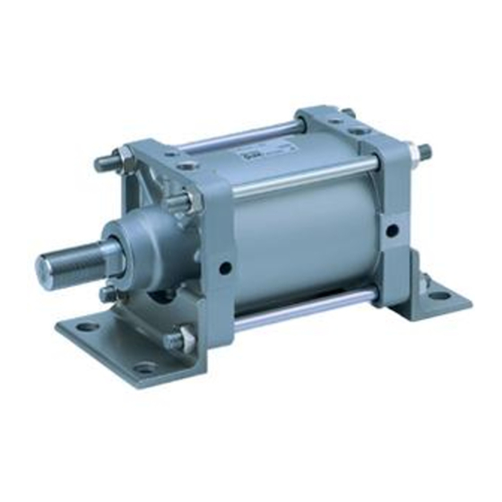
- Page 1 付表 3 Doc. no. CS2*-OM0237Q PRODUCT NAME AIR CYLINDER MODEL / Series / Product Number 25A-CS2*125~160-**...
-
Page 2: Table Of Contents
付表 3 Contents 1. Safety Instructions 2. Product specifications 1) Specifications 2) Max. stroke 3) Max. usable stroke by the side load given to the cylinder 4) The relation between cylinder size and max. stroke by the mounting style 5) Theoretical output 6) Kinetic energy absorbed by cushion mechanism 7) How to order P.10... -
Page 3: Safety Instructions
付表 3A Safety Instructions These safety instructions are intended to prevent hazardous situations and/or equipment damage. These instructions indicate the level of potential hazard with the labels of “Caution,” “Warning” or “Danger.” They are all important notes for safety and must be followed in addition to International Standards (ISO/IEC) , and other safety regulations. - Page 4 付表 3A Safety Instructions Caution The product is provided for use in manufacturing industries. The product herein described is basically provided for peaceful use in manufacturing industries. If considering using the product in other industries, consult SMC beforehand and exchange specifications or a contract if necessary.
-
Page 5: Product Specifications
2 Product Specifications 1) Specifications Fluid Max. operating pressure 0.97MPa Proof pressure 1.57MPa Min. operating pressure 0.05MPa 0.05~0.5m/sec Piston speed Cushion With cushion Ambient and fluid 0~70℃(No freezing) temperature Thread tolerance JIS Class 2 +1.0 ㎜ ~ 250 ㎜ 0 +1.4... -
Page 6: Max. Stroke
2) Max. stroke Table 1. Maximum stroke (mm) Basic Bracket Head side flange, Foot, Single clevis Rod side flange Double clevis Bore size Center trunnion φ125 1000 or less 1600 or less φ140 1000 or less 1600 or less φ160 1200 or less 1600 or less !... - Page 7 Ex.) 25A-CS2F125-300 According to the graph 1, nodal point of cylinder stroke 300mm and Φ125 is 115N. Lateral load to rod end needs to be smaller than this. Graph 1:Allow lateral load 1000 φ160 φ125&140 1000 1500 2000 Stroke(mm) ⅱ Judging lateral load of dead weight In case of rotating type cylinder, lateral road applies to the piston rod because of dead weight of the cylinder.
-
Page 8: The Relation Between Cylinder Size And Max. Stroke By The Mounting Style
φ125 to φ160 4) The relation between cylinder size and max. stroke by the mounting style Table 2 shows max. usable stroke found by calculation on the assumption that the force generated by cylinder itself acts on piston rod or piston rod and tube as buckling force. - Page 9 Table 2. Usable stroke by buckling strength Usablestroke by Mounting style buckling strength (cm) Pressure Symbol and sketch (MPa) φ125 φ140 φ160 Symbol of bracket Head 0.3 side L side Foot: Frang flange ・ 0.5 F 0.7 0.3 G 0.5 0.7...
-
Page 10: Theoretical Output
OUT IN Theoretical output (N) Table 3. Double acting cylinder theoretical output Operating pressure(MPa) Bore Pressurized Operating size area diameter direction (mm) (mm) (mm ) 12300 3690 6150 8610 11100 11500 3440 5750 8030 10300 15400 4620 7700 10200 13900 14600... -
Page 11: How To Order
7) How to order B 125 D-M9* Auto-switch Stroke Bore size Mounting bracket Built-in magnet Secondary battery production facility Air Cylinder Built-in magnet Bore size Built-in magnet 125mm Without magnet 140mm 160mm Mounting Basic Stroke Foot *Refer to Maximum stroke table(P5 Table 1) Front flange Head side flange Auto-switch... - Page 12 3. Use the product within the specified range of fluid and ambient temperature. Take measures to prevent freezing, since moisture in circuits will be frozen under 5℃, and this may cause damage to seals and lead to malfunction. Refer to SMC’s “Air Cleaning Equipment” catalog for further details on compressed air quality.
- Page 13 9. Design circuitry to prevent sudden lurching of driven objects. When a cylinder is driven by an exhaust center directional control valve or when starting up after residual pressure is exhausted from the circuit, etc., the piston and its driven object will lurch at high speed if pressure is applied to one side of the cylinder because of the absence of air pressure inside the cylinder.
-
Page 14: Operating Environment
3) Mounting Caution ! 1. Make sure to connect the piston rod and the load so that their axial center and movement directions match. If they do not match, stress could be applied to the piston rod and the cylinder tube, causing the inner surface of the cylinder tube, the bushing, the piston rod surface, and the seals to wear and to become damaged. -
Page 15: Piping
4. Do not store cylinders in humid places. Humid environment should be avoided when storing cylinders. Before storing cylinder, be sure to retract its piston rod in a low humid place to avoid rust generation. 5) Piping Figure 1 is a basic circuit when operating a cylinder with air filter, regulator, solenoid valve and speed controller. -
Page 16: Cushion
3. Screwing of fitting When screwing the fitting into the port, tighten by the following appropriate torque. Table 5 Tighten torque of piping Tightening torque Port size N・m 28~30 Rc 1/2,NPT 1/2 28~30 Rc3/4,NPT3/4 6) Cushion ! Warning 1) A deceleration circuit or shock absorber, etc., may be required. When a driven object is operated at high speeds or the load is heavy, a cylinder’s cushion will not be sufficient to absorb the shock. -
Page 17: Speed Control
3 . If the cushion valve is fully closed throughout operation, the piston may bounce at the stroke end, not move full stroke, or the cushion seal may be damaged due to excessive pressure. Therefore, do not use the cushion cover in such manner. -
Page 18: Maintenance
2. Intermediate stops When intermediate stopping of a cylinder piston is performed with a 3 position closed center type directional control valve, it is difficult to achieve stopping positions as accurate and minute as with hydraulic pressure, due to the compressibility of air. -
Page 19: Overhaul
2) Overhaul When abnormality is found by regular inspection, following portions should be inspected and take corrective action. However, seal kits should be replaced. Table 6. Portion to be inspected, abnormality and corrective action Portion to be Abnormality Corrective action inspected No problem with operation. -
Page 20: Assembly
5. Loose either of nuts for tie rod with “ratchet handle for socket wrench”, “T-type slide handle for socket wrench” or “spinner handle for socket wrench”, etc. and remove it from the tie rod. Please refer to the table 7 for “socket for socket wrench. Table.7 Socket Tube bore size Applicable socket... -
Page 21: Expendable Supplies
Tie rod Foot bracket Rod cover or head cover Figure 3 9. Tighten tie rod and bolt with appropriate torque shown in the table 8. (N・m) Table 8. Tightening torque φ125 φ140 φ160 Bore size 39.2 62.8 Tightening torque 5) Expendable supplies 1.Part No. -
Page 22: Replacement Procedure Of Seal
a. Seal kits should be packed in sealed up condition and stored. b. When removing a part of the seal kits, pack the remained items again so that the package condition will be restored to its former state as much as possible with care to protect them from foreign matters. Don’t store the remained items without sealing. -
Page 23: Inspection
a. Cushion seal/Rod seal Mount in correct direction. b. Seal kits (O-ring) other than Rod seal and Cushion seal After mounting seal kit, apply grease on inside diameter surfaces of bushing (rubbing grease into surface). 7) Inspection 1. Follow the procedure of the table 11 for inspection after assembly. Table 11. -
Page 24: Troubleshooting
Troubleshooting Table 12. Troubleshooting Failure Main cause Measure 1. Operation ●Disassemble and apply applicable grease is not 1. Improper lubrication (lithiumsoap group grease JIS #2 ) smooth. ●Rod deformation is caused by offset load, side load, over load, abnormal displacement of mounting 2. - Page 25 Failure Main cause Measure ●Use larger valve. 4. Piston 1. Directional control operates valve size of too slow. too small. ● Use appropriate size valve and other equipment. 2. Resistance of the Pay extreme attention to the size of piping material equipment used for and fitting.
- Page 26 Failure Main cause Measure ● Operation at high speed may deform or damage Deformation 1. Speed is too fast. the piston rod due to impact force. Operate the cylinder within the high speed limit range. ● Generation of inpulsive sound at the stroke end breakage of 2.
-
Page 27: Construction
6. Construction Figure-4 Table. 13 Parts list * is different from standard type (C(D)S2) Name Material Note Rod cover Die-cast alminum Chromated Head cover Die-cast alminum Chromated Cylinder tube Aluminum alloy Hard anodized Piston Aluminum alloy Chromated Piston rod Carbon steel Hard chrome plating *Bushing Iron-based sintered alloy... - Page 28 Figure -5 Mounting bracket: Single clevis (C) Table -14 Parts list (The item with * mark is different from the basic type 25A-C (D) S2. The item with ★ mark is the part that is out of the applicable range of the specifications for secondary batteries.
- Page 29 Figure -7 Mounting bracket: Front flange (F) Table -16 Parts list (The item with * mark is different from the basic type 25A-C (D) S2. The item with ★ mark is the part that is out of the applicable range of the specifications for secondary batteries.
- Page 30 Figure -9 Mounting bracket: Foot (L) Table -18 Parts list (The item with * mark is different from the basic type 25A-C (D) S2. The item with ★ mark is the part that is out of the applicable range of the specifications for secondary batteries.
-
Page 31: Auto Switch Precautions
Fig. -11 Auto switch mounting bracket (For 125, 140: 25A-BA6-125 / for 160: 25A-BA6-160) Table -20 Parts list (The above auto switch mounting bracket is used only for auto switch type. Item with * mark is standard. ) Item Material Qty. - Page 32 Table 22 Reed auto switch Mounting Auto switch Indicator Electrical Voltage, current Application method to model light entry the cylinder IC circuit DC4.5~28V , Relay Tie-rod D-M9N-900 Grommet Max.40mA Sequence mounting controller IC circuit DC4.5~28V , Relay Tie-rod D-M9NV-900 Grommet Max.40mA Sequence mounting...
-
Page 33: Precautions For Use
Precautions for use When installing the auto switch on the 25A-CDS2 series, pay attention to the following. 1. Do not let the auto switch drop or apply with an excessive impact to it when handling. 2. Do not use the product in the presence of a strong magnetic field. 3. - Page 34 付表 3B Revision history 4-14-1, Sotokanda, Chiyoda-ku, Tokyo 101-0021 JAPAN Tel: + 81 3 5207 8249 Fax: +81 3 5298 5362 https://www.smcworld.com Note: Specifications are subject to change without prior notice and any obligation on the part of the manufacturer. ©...
Need help?
Do you have a question about the CS2 and is the answer not in the manual?
Questions and answers