Table of Contents
Advertisement
Quick Links
Advertisement
Table of Contents

Related Manuals for SMC Networks CJP2 Series


Summary of Contents for SMC Networks CJP2 Series
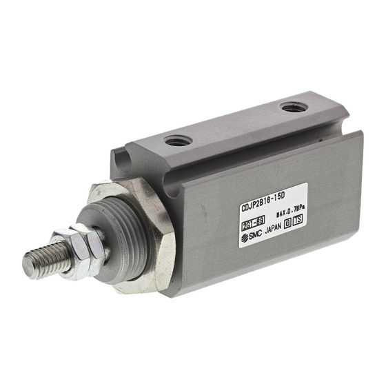
- Page 1 No. CJP2-OM0002K-A OPERATION MANUAL PIN CYLINDER 【CJP2 Series】 Φ4,Φ6,Φ10,Φ16 ☆Read this manual thoroughly before mounting and operating the actuator. ☆Pay particular attention to the section concerning safety. ☆Keep this manual in an accessible location. SMC Corporation...
-
Page 2: Table Of Contents
Contents 1.Safety Instructions ・・・・・・・・・・・・・・・・・・・・・・・・・・・・・・・・・・・・・・・・・・・・・・・・・・・・・・・・・ P.1 2.Specifications ・・・・・・・・・・・・・・・・・・・・・・・・・・・・・・・・・・・・・・・・・・・・・・・・・・・・・・・・・・・・・ P.3 2-1.Specifications 3.Precautions ・・・・・・・・・・・・・・・・・・・・・・・・・・・・・・・・・・・・・・・・・・・・・・・・・・・・・・・・・・・・・・・ P.4 Caution on Design 3-1. Selection 3-2. Mounting 3-3. Piping 3-4. Lubrication 3-5. Air Supply 3-6. Operating Environment 3-7. Maintenance 3-8. Rotation angle 3-9. Snap ring installation/removal 3-10. Auto switches 3-11.... -
Page 3: 1.Safety Instructions
1.Safety Instructions These safety instructions are intended to prevent a hazardous situation and/or equipment damage. These instructions indicate the level of potential hazard by labels of "Danger ", "Warning" or "Caution ". To ensure safety, be sure to observe ISO 4414 , JIS B 8370 and other safety practices. - Page 4 Contact SMC if the product is to be used in any of the following conditions: ④ 1.Conditions and environments beyond the given specifications, or if product is used outdoors or placed where direct sunshine strikes. 2 .Installation on equipment in conjunction with atomic energy, railway, air navigation, vehicles, medical equipment, food and beverages, recreation equipment, emergency stop circuits, clutch and brake circuits in press applications, or safety equipment.
-
Page 5: 2.Specifications
2.Specifications 2-1.Specifications Bore size (mm) Action Double acting,Single rod Max.operating pressure 0.7MPa Min.operating pressure 0.15MPa 0.12MPa 0.06MPa Proof pressure 1.05MPa Without auto switch:-10~70℃ Ambient and fluid temperature With auto switch:-10~60℃ (No freezing) Lubrication Not required (Non-lube) Stroke length tolerance Thread tolerance JIS Class 2 Rod end configuration With thread / Without thread... -
Page 6: 3.Precautions
3.Precautions 3-1.Caution on Design Warning ① There is a possibility of dangerous sudden action by air cylinders if sliding parts of machinery are twisted due to external forces, etc. In such cases, human injury may occur; e.g., by catching hands or feet in the machinery, or damage to the machinery itself may occur. - Page 7 Caution ① Do not wipe off the grease attached on the sliding face of the cylinder. If the grease is removed from the sliding part of the cylinder forcibly, a malfunction could occur. When the cylinder has been in operation for a long distance, the sliding parts become discolored black.. In such cases, to prolong cylinder life, wipe off the grease from the sliding parts, and add new grease.
-
Page 8: 3-2.Selection
3-2.Selection Speed control When cylinder is adjusted to desired speed, install speed controller such as SMC’s AS series near supply port of air. For this adjustment, either of supply air or exhaust air is squeezed, generally exhaust air is done. Direction control When actuatig direction of cylinder is changed, install adequate solenoid valve selected among SMC’s various models. -
Page 9: 3-3.Mounting
3-3.Mounting Caution ① Be certain to match the rod shaft center with the load and direction of movement when connecting. When not properly matched, problems may arise with the rod and body, and damage may be caused due to friction on areas such as the inner body surface, bushings, rod surface, and seals. ②... - Page 10 ⑨ When the cylinder and bracket are mounted, do not exceed the max. tightening torque stated below. At the same time, the thickness of the panel used for mounting should be less than the max. A dimension shown in the following table. Bore size Thread size Max.tightening torque(N・m)
- Page 11 ⑩ When a load, cap, single knuckle joint or double knuckle joint is mounted on the end of the rod, do not exceed the max. tightening torque in the following table. Bore size Thread size Max.tightening torque(N・m) Φ4 M2×0.4 Φ6 M3×0.5 Φ10 M4×0.7...
-
Page 12: 3-4.Piping
3-4.Piping Caution ① Before piping Before piping, it should be thoroughly blown out with air (flushing) or washed to remove chips, cutting oil and other debris from inside the pipe. ② Wrapping of pipe tape When screwing piping or fittings into ports, ensure that chips from the pipe threads or sealing material do not get inside the piping. -
Page 13: 3-6.Air Supply
3-6.Air Supply For compressed air supplied to the cylinder, use the air which is filtrated by SMC’s filter such as AF series and adjust to specified setting pressure by SMC’s regulator such as AR series. Warning ① Use clean air. Do not use compressed air which contains chemicals, synthetic oils containing organic solvents, salts or corrosive gases, etc., as this can cause damage or malfunction. -
Page 14: 3-8.Maintenance
3-8.Maintenance Warning ① Perform maintenance procedures as shown in the instruction manual. If they are handled improperly, malfunction or damage of machinery or equipment may occur. ② Removal of equipment, and supply/exhaust of compressed air Before any machinery or equipment is removed, first ensure that the appropriate measures are in place to prevent the falling or erratic movement of driven objects and equipment, then cut off the electric power and reduce the pressure in the system to zero. -
Page 15: 3-10.Snap Ring Installation/Removal
3-10.Snap ring installation/removal Caution ① To replace seals or grease the cylinder during maintenance, use an appropriate pair of pliers (tool for installing a type C snap ring for hole). After re-installing the cylinder, make sure that the snap ring is placed securely in the groove before supplying air. -
Page 16: 3-11.Auto Switches
3-11.Auto switches The type and specifications of applicable auto switch and the cautions for handling them can be found in the catalogue and operation manual respectively. ① Proper Auto Switch Mounting Position (Detection at stroke end) and Its Mounting Height ≒H * When a screw is not mounted on the end of the rod, a nut cannot be mounted. - Page 17 ② The amount of protrusion of the auto switch Mounting: Basic style,Flange style,Foot style D-M9□ D-M9□V D-A90 D-A93 D-M9□W D-M9□WV D-A96 D-A9□V Φ4 ― ― Φ6 Φ10 Φ16 Mounting: Clevis style,Trunnion style D-M9□ D-M9□V D-M9□W D-M9□WV D-A9□ D-A9□V Φ4 ― ―...
- Page 18 ③ Operating Range Unit:mm (at 25℃) * Since this is a guideline that Φ4 Φ6 Φ10 Φ16 includes hysteresis, it is not meant to be guaranteed. D-A9□ ― (Assuming approximately a D-A9□V ±30% dispersion) D-M9□ Substantial changes may be D-M9□V needed depending on the D-M9□W ambient environment.
- Page 19 ⑤ Auto switch mounting Mounting screw Watchmakers’ screwdriver Auto switch ①Fit an auto switch mounting groove to set it roughly to the mounting position for an auto switch. ②After confirming the detedting position, tighten up the mounting screw attached to an auto switch, and secure the seitch.
-
Page 20: 4.Model Selection
4.Model selection 4-1.Allowable Kinetic Energy Caution When driving an inertial load, operate a cylinder with kinetic energy within the allowable value. The range in the chart below that is delineated by bold solid lines indicates the relation between load weights and maximum driving speeds. Bore size Φ4 Φ6... -
Page 21: 4-2.Lateral Load At Rod End
4-2.Lateral Load at Rod End Caution In principle, the load applied to the piston rod should always be kept in the axial direction. If this situation cannot be avoided, keep the lateral load applied on the bushing of the cylinder, to 1/50 or less of the maximum output of the cylinder. -
Page 22: 5.Pneumatic Circuit
5.Pneumatic circuit The typical circuit for CJP2 series where air filter, regulator, solenoid valve and speed controller (meter-out) are used for operation is as follows. Pressure gauge Speed Pressure controller Regulator source Air filter Drain catch Mist separator Air tank... -
Page 23: 6.Maintenance And Check
6.Maintenance and Check 6-1.Daily check ①Is the operation smooth? ②Is there any abnormal change in the piston speed and cycle time? ③Is there any abnormality in the stroke? 6-2.Periodic check ①Are the cylinder mounting bolts and workpieces firmly fixed? ②Is the operation smooth? ③Are there any abnormal changes in the piston speed and cycle time? ④Is there any external leakage? ⑤Is there any abnormality in the stroke? - Page 24 2.Removal of the seal ①Rod seal Insert a precision driver etc. from front the body and prise the seal out. Take care not to scratch or score the seal groove in the body. Do not scratch groove ②Piston seal Push the tube gasket partially to make it come off and pull it out manually. Pick and pull ③Gasket(See above) Push the gasket partially to make it come off and pull it out manually.
- Page 25 4.Mounting of seal ①Rod seal Mount the rod seal with attention to direction. Then, apply the grease on the seal evenly. Body bushing Grease ②Piston seal When mounting the seal, ensure there are no twists in the seal. Also add the grease inside the groove. Grease ③Gasket Pay attention not to make the gasket come off.
-
Page 26: 6-4.Consumable Parts
6.Reassembly of the cylinder ①Insertion of piston rod ASS 'Y Please insert piston rod ASS 'Y in the body. ②Insertion of head cover ASS 'Y Please insert head cover ASS 'Y in the body. ③Mounting of the snap ring Mount the snap ring with proper pliers. ④Check the assembly condition. -
Page 27: 6-5.Bracket
6-5.Bracket Foot, Flange and trunnion were prepared in this product. Foot Bore size (mm) Kit no. CP-L006A CP-L010A Foot (1 pc.) CP-L016A *Material of foot is iron. *Please consult separately about for Φ4. Flange Bore size (mm) Kit no. CP-F006A CP-F010A Flange (1 pc.) CP-F016A... -
Page 28: 6-6.Accessory Bracket
6-6.Accessory Bracket Single knuckle joint, Double knuckle joint, Knuckle pin, Trunnion pin, Mounting nut, Rod end nut and Rod end cap (Flat type, Round type) were prepared in this product. Single knuckle joint Bore size (mm) Kit no. I-P006A I-P010A Single knuckle joint (1 pc.) I-P016A *Material of single knuckle joint is iron. - Page 29 Mounting nut Bore size (mm) Kit no. SNPS-004 SNP-006 Mounting nut (1 pc.) SNP-010 SNP-015 *Material of mounting nut is brass. Rod end nut Bore size (mm) Kit no. NTJ-004 NTP-006 Rod end nut (2 pcs.) NTP-010 NTP-015 *Material of rod end nut is steel. Rod end cap (Flat type) Bore size (mm) Kit no.
-
Page 30: 7.Troubleshooting
7.Troubleshooting Related Trouble Phenomenon Possible cause Remedy section ・The operation is not Air leakage 1、The rod seal is damaged by flaws 1、Replace piston rod and rod seal. smooth. (external) on the piston rod. 2、Apply the grease on piston rod ・The force output is 2、The rod seal is damaged by a lack and replace seal. -
Page 31: 8.Basic Construction
8.Basic construction Φ4 With auto switch Magnet holder Brass Magnet Magnetic material Rod seal Piston seal Bumper Urethane Rod end nut Steel Nickel plated Mounting nut Brass Electroless nickel plated Snap ring Tool steel Phosphate coated Seal holder Special-purpose steel Nickel plated Gasket SUS+NBR... - Page 32 Φ6 With auto switch Magnet holder Brass Magnet Magnetic material Gasket Rod seal Piston seal Bumper Urethane Rod end nut Steel Nickel plated Mounting nut Brass Electroless nickel plated Snap ring Tool steel Phosphate coated Piston Brass Piston rod Stainless steel Head cover Brass Electroless nickel plated...
- Page 33 Φ10・16 With auto switch Aluminum alloy Φ16:Chromated Magnet holder Brass Φ10 Magnet Magnetic material Piston gasket Gasket Rod seal Piston seal Bumper Urethane Rod end nut Steel Mounting nut Brass Electroless nickel plated Snap ring Tool steel Phosphate coated Aluminum alloy Φ16:Chromated Piston Brass...
- Page 34 Revision 4-14-1, Sotokanda, Chiyoda-ku, Tokyo 101-0021 JAPAN Tel: + 81 3 5207 8249 Fax: +81 3 5298 5362 http://www.smcworld.com Note: Specifications are subject to change without prior notice and any obligation on the part of the manufacturer. © 2011 SMC Corporation All Rights Reserved...
Need help?
Do you have a question about the CJP2 Series and is the answer not in the manual?
Questions and answers