
Related Manuals for SMC Networks CY1L Series


Summary of Contents for SMC Networks CY1L Series
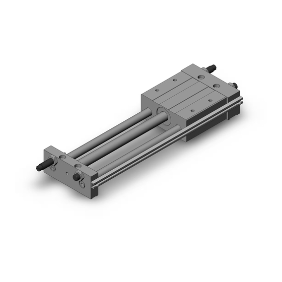
- Page 1 Doc. no. CY*L-OM0002C PRODUCT NAME Magnetically Coupled Rodless Cylinder (Slider Type: Ball Bushing Bearing) MODEL / Series / Product Number CY1L Series...
-
Page 2: Table Of Contents
Contents Safety Instructions 1. How to install 1-1. Surface to be installed 1-2. Installation procedure 1-3. Piping 1-4. Precautions to use with auto switch. 1-5. How to use the adjust bolt (with damper) 1-6. Precautions to use with shack absorber 2.Allowable loads and its selection method 2-1. - Page 3 Safety Instructions These safety instructions are intended to prevent hazardous situations and/or equipment damage. These instructions indicate the level of potential hazard with the labels of “Caution,” “Warning” or “Danger.” They are all important notes for safety and must be followed in addition to International Standards (ISO/IEC) , and other safety regulations.
- Page 4 Safety Instructions Caution We develop, design, and manufacture our products to be used for automatic control equipment, and provide them for peaceful use in manufacturing industries. Use in non-manufacturing industries is not covered. Products we manufacture and sell cannot be used for the purpose of transactions or certification specified in the Measurement Act.
-
Page 5: How To Install
1.How to install 1-1. Surface to be installed The surface to be installed is required to have high flatness, but in case the flatness is not sufficient, the installation should be performed in order to enable the slide block (movable carriage) travel under the minimum operating pressure by shi adjusting or other means. -
Page 6: Piping
1-3. Piping The piping port is on the plate A (thinner plate) with capability of concentrated piping. However, it is not available on the plate B (thicker plate). Explanation for models with auto switch Although the piping ports are located at one side, the mounting rail for the auto switch can be mounted on either side. - Page 7 contact point etc. Refer to the catalog of Rodless cylinder (CY1 series). 1-5. How to use the adjust bolt (damper). The adjustment of stroke can be performed at the stroke end by the standard adjust bolt. Thinking of durability, its operation to stop by adjust bolt is advised within range of loads and velocity shown in the following Fig.
-
Page 8: Precautions To Use With Shack Absorber
1-6. Precautions to use with shock absorber 1-6-1) Both shock absorber and adjust bolt can be installed together. 1-6-2) Adjustment is possible at stroke end by shock absorber as by adjust bolt. Note) About adjusting span, please refer to Table 1. 1-6-3) Screws at bottom of the body, shock absorber must not be turned (they are not adjustment screw),loosening those may cause leakage. -
Page 9: Allowable Loads And Its Selection Method
2.Allowable loads and its selecting method. 2-1. About selection procedures. Selection procedures of CY1L* (Ball bushing type) - Page 10 2-2. Information to select Rodless Cylinder (CY1L: Ball bushing type)
- Page 11 Note) Safety factor is taken into consideration to prevent from falling.
-
Page 14: Intermediate Stop
3. Regarding intermediate stop 3-1. In case to stop by external stopper (adjust bolt, shock absorber and etc…) Care should be taken for the followings, when it’s stopped at half-way of the stroke by external stopper (adjust bolt, shock absorber and etc…) 3-1-1) Maximum working pressure Operation of this device should be performed within stated figure in Table 3. - Page 15 In such case occurred, relieve half-way stop inunctions and at stroke end push travel part manually (or apply equivalent pressure to holding force to travel part at piston side) to right position. 3-2. In case to stop intermediately using by pneumatic circuit To stop intermediately by pneumatic circuit, following cares should be taken.
-
Page 16: Operating Air
4. Operating air 4-1. Since this cylinder is non-lube type, air to be supplied should be filtered by SMC made AF Series air filter and be regulated by AR Series regulator. When it is needed to lubricate, please check our website for the brands of each company’s class 1 turbine oil (with no additives) and class 2 (with additives). -
Page 17: Other Precautions
Fig7. Direction of the travel parts 5-5. When handle magnet assembly, watch on your arm should be put off (particularly analog one) not to get influence from strong magnetic field. 5-6. Through care should be taken for the magnet not to drop on the floor or knock against metal. - Page 19 Revision history Tel: + 81 3 5207 8249 Fax: +81 3 5298 5362 https://www.smcworld.com Note: Specifications are subject to change without prior notice and any obligation on the part of the manufacturer. © SMC Corporation All Rights Reserved...
Need help?
Do you have a question about the CY1L Series and is the answer not in the manual?
Questions and answers