Advertisement
Quick Links
OPERATION MANUAL
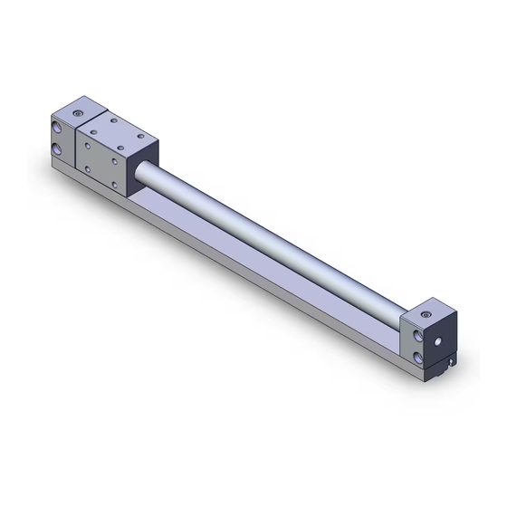
TITLE: Rodless Cylinder
○Read this manual thoroughly before mounting and
operation.
○Especially,carefully read the description concerning
safety.
○Keep this manual where accessible when necessary.
SMC CORPORATION
N o .
CY3R Series
C Y * R - O M 0 0 0 1 H - A
FORMAT No.FOM007-2
1 / 1 7
Advertisement

Related Manuals for SMC Networks CY3R Series


Summary of Contents for SMC Networks CY3R Series
- Page 1 N o . C Y * R - O M 0 0 0 1 H - A 1 / 1 7 OPERATION MANUAL TITLE: Rodless Cylinder CY3R Series ○Read this manual thoroughly before mounting and operation. ○Especially,carefully read the description concerning safety....
- Page 2 INDEX 1.Installation to Application 3 2.Actuating Force and Moment 10 3.Vertical Operation 11 4.Immediate Stop 12 5.Operating Air and Piping 13 6.Disassembly and Maintenance 13 7.Other Cautions for Operation 14 8.Made to Order 14 9.Internal Construction and Parts List 15...
-
Page 3: Safety Instructions
付表 3A Safety Instructions These safety instructions are intended to prevent hazardous situations and/or equipment damage. These instructions indicate the level of potential hazard with the labels of “Caution,” “Warning” or “Danger.” They are all important notes for safety and must be followed in addition to International Standards (ISO/IEC) , and other safety regulations. -
Page 4: Limited Warranty And Disclaimer/Compliance Requirements
付表 3A Safety Instructions Caution 1. The product is provided for use in manufacturing industries. The product herein described is basically provided for peaceful use in manufacturing industries. If considering using the product in other industries, consult SMC beforehand and exchange specifications or a contract if necessary. - Page 5 1.Installation to Application The rodless cylinder presented in this manual can operate the load directly mounted on it without other axes in a range of allowable mounted load, moment and stroke if it is equipped with the switch rail. (Table1,2) (P8,9) However, without the switch rail, the load needs to be guided by other axes (LM guide etc.) to prevent rotation of external slider and direct application of the load over the allowable range.
- Page 6 1-2) Installation of external slider and load Same as installation of the cylinder body, there are two ways to install the external slider and load in a range of allowable mounted load, moment and stroke. (Ⅰ) With other axes combined (Ⅱ) Without other axes combined (Switch rail is used as non-rotation device.) (Ⅰ) With other axes combined...
- Page 7 Ⅰ-b) The misalignment between cylinder body and guide (orbit) may be caused depending on machining accuracy of the space for mounting. Therefore, the installation must be performed to compensate the misalignment. The following two show the example with or without concern about misalignment respectively.
- Page 8 A B Guide shaft Bearing Load base Cylinder tube External slider Detail of A Wrong example Correct example Detail of A Load base Load base External slider Spacer External slider Clearance Detail of B Detail of B By tightening of the bolt, the load base and Insert the spacer to keep flexibility in cylinder cylinder body are in the state similar to direct body and load base even after the bolt is tightened.
- Page 9 Wrong example Correct example Guide by linear guide Load Direct fix Load Guide shaft The load is supported by guide shaft and the Since the cylinder is subject to direct moment of clearance is provided to compensate misalignment. load, guide shaft can work as only non-rotation The bracket is longer than center of axis of cylinder and operating failure may be caused.
- Page 10 The misalignment can be checked by the following procedure. 1) After installation of cylinder to application, increase pressure of regulator gradually before checking operation of cylinder at operating pressure, and then calculate min. pressure which enables smooth operation of cylinder over full stroke. Adjust to minimize this increase.
- Page 11 Table 2 Non-rotation accuracy and max. allowable moment at stroke end (reference) Max. allowable Non-rotation Note 2) Cylinder tube moment accuracy Allowable stroke I.D. (mm) (N・m) (°) φ6 0.02 φ10 0.05 φ15 0.15 φ20 0.20 φ25 0.25 φ32 0.40 Fig.6-2 Non-rotation accuracy direction φ40 0.62 φ50...
- Page 12 2.Actuating force and moment 2-1) Actuating force The actuating force of rodless cylinder is ideally equal to thrust at center of axis of piston but normally, as shown on Fig. 7-1, it is taken as FnN at the part away from the center Load by Locm.
-
Page 13: Vertical Operation
2-2) Moment at stroke end 3.Vertical Operation If the rodless cylinder is used for the load If the cylinder is operated in vertical direction, with large inertia, the following operating consider the same points as section 2. failures may be caused at stroke end. As shown on Fig. -
Page 14: Intermediate Stop
4.Intermediate Stop 4-1) Consider the following point to stop the load on the way of stroke by external stopper etc. a) Operating pressure Table 4 Operating pressure Keep operating pressure below the limit limit for intermediate stop shown on Table 4. The operation at higher pressure may cause thrust over holding Cylinder Operating... - Page 15 5.Operating Air and Piping 6-1) If the cylinder body or piston is removed 5-1) Install air filter. from cylinder tube, displace the positions The rodless cylinder is non-lubrication type. Install air filter to upstream near the valve and of external slider and piston forcedly to adjust pneumatic pressure decreased to eliminate holding force and take out them desired set pressure by regulator.
- Page 16 7.Other Cautions for Operation 7-1) Some of internal components of cylinder is made of iron. Protect them from direct splash of water etc. If such a situation can’t be avoided, contact SMC separately. 7-2) Before piping, perform flashing inside the piping to prevent intrusion of dust and cutting chip inside the cylinder.
- Page 17 9.Internal Construction and Parts List 9-1) CY3R series (both-side piping)
- Page 18 9-2) CY3RG series (Common piping)
- Page 19 9-3) If the switch rail needs to be mounted to the cylinder, it can be ordered as accessory in accordance with the following numbering system. How to order switch rail as accessory CYR15E- Stroke Cylinder tube I.D.
- Page 20 Revision 4-14-1, Sotokanda, Chiyoda-ku, Tokyo 101-0021 JAPAN Tel: + 81 3 5207 8249 Fax: +81 3 5298 5362 http://www.smcworld.com Note: Specifications are subject to change without prior notice and any obligation on the part of the manufacturer. © 2011 SMC Corporation All Rights Reserved...
Need help?
Do you have a question about the CY3R Series and is the answer not in the manual?
Questions and answers