Minuteman EN750, EN900 - Enspire Series UPS Manual
- User manual (2 pages)
- Also fits for
- En900
- Enspire en750
- Enspire en900
- Enspire series
Advertisement
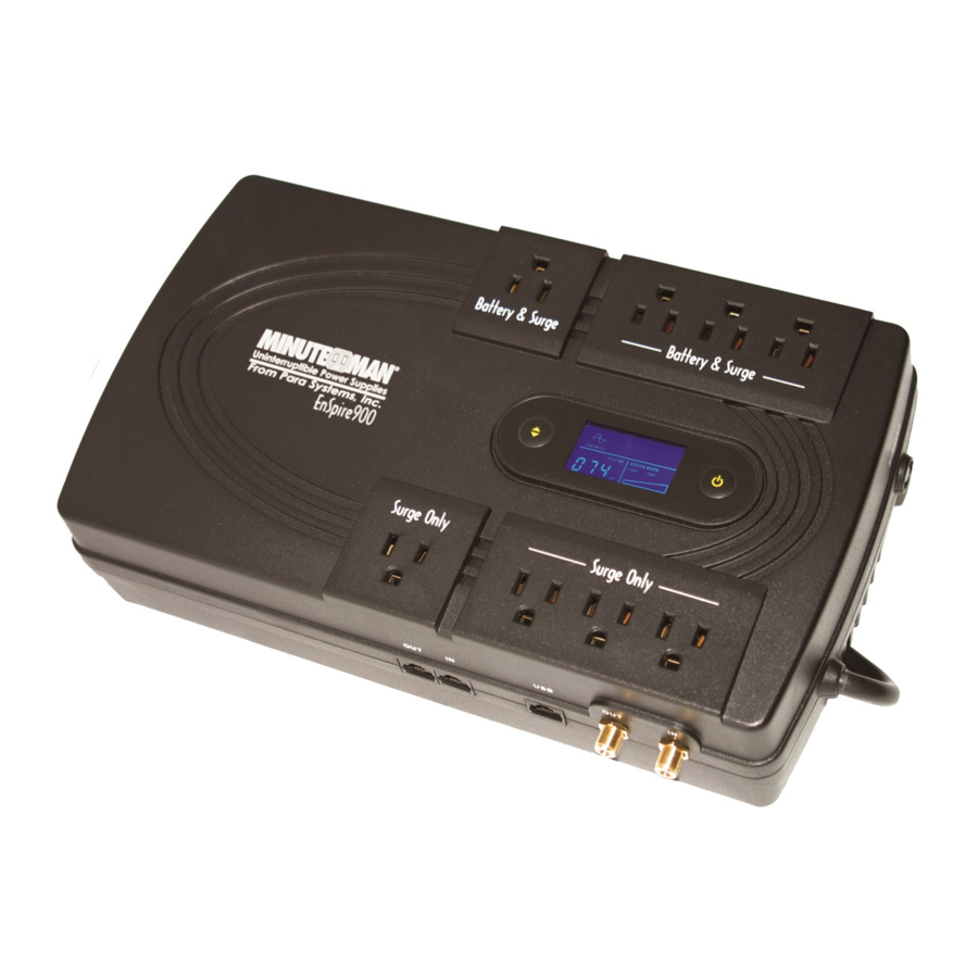
CONTROLS AND INDICATORS

- Battery Backup and Surge output power receptacles: for mission critical equipment.
- Input circuit breaker: for overload protection. If the output load exceeds the UPS's power rating the breaker will trip.
- Scroll button: to scroll through the LCD display and to silence the alarm in the Battery mode. When the UPS is in the Battery mode hold the Scroll button down until the Alarm Silencer icon appears on the LCD and then release.
- On/Off Button: to turn the UPS On/Off.
- The LCD Display has visual (icons) and numerical information. The icons are AC mode, On Battery mode, Alarm Silence (Battery Mode only), Fault, and a dual-function bar graph for Load capacity (AC mode) and Battery capacity (DC mode). The numerical information is Input/Output voltage and frequency, and the estimated battery runtime.
- Input Power Cord: to connect to utility power.
- Surge Only output power receptacles: for non-mission critical equipment.
- RJ-11/45 modular connectors: for single line phone/fax/modem protection.
- USB port: for USB communications to monitor and control the UPS. The USB Protocol is HID. The USB port operates with the standard Windows USB drivers and does not require any additional USB drivers.
- Coaxial connectors: for transient voltage surge suppression for cable modem, CATV converter or DSS receiver.
| Model # | Input Power Plug | Output Power Receptacles |
| EN750 | NEMA 5-15P W/6 ft cord | 4-NEMA 5-15R Surge Only |
| EN900 | 4-NEMA 5-15R Battery Backup & Surge |
INSTALLATION

This UPS series is intended to be install in a temperature controlled environment that is free of conductive contaminants. Select a location which will provide good air circulation for the UPS at all times. Avoid locations near heating devices, water or excessive humidity, or where the UPS is exposed to direct sunlight. Route power cords so they cannot be walked on or damaged.
ENVIRONMENTAL
| Operating Temperature: Operating Elevation: | 0 to 40 degrees C (+32 to +104 degrees F) at 0 to 1,000m (0 to +3,333 ft) |
| Operating Temperature: Operating Elevation: | 0 to 35 degrees C (+32 to +95 degrees F) at 1001 to 3,000m (+3,334 to +10,000 ft) |
| Storage Temperature: | -15 to +45°C (+5 to +113°F) |
| Operating/Storage Humidity: | 95% Non-Condensing |
| Storage Elevation: | 0 to 15,000m (0 to +50,000 ft) |
| Audible Noise at 1 m (3 ft.): | <45 dBA |
INSTALLATION
Be sure to read the installation placement and all the cautions before installing the UPS. Place the UPS in the final desired location and complete the rest of the installation procedure. These UPSs are shipped with the internal batteries disconnected. The batteries must be connected before putting these UPSs into service. See the Connecting The Batteries procedure to connect the batteries.
CONNECTING THE BATTERIES
(QUALIFIED SERVICE PERSONNEL ONLY)
Please read all of the  and
and  before attempting to connect the batteries.
- Remove the UPS from the shipping box and set on the floor or a bench top.
- Place the UPS receptacle side down.
- Remove the battery compartment door retaining screw. (FIG. 1)

- Remove the battery compartment door by pressing down on the locking tabs, slide the door outwards and then lift up. (FIG. 2)

- Verify proper polarity. Connect the battery negative (Black) wire to the battery negative terminal. (FIG. 3)

NOTE: Some sparking might occur, this is normal. - Re-install the battery compartment door onto the UPS.
![]()
DO NOT pinch the battery wires with battery compartment door. - Re-install the battery compartment door retaining screw.
- Continue with the rest of the Installation.


WALLMOUNTING
The wallmount configuration allows the user to mount the UPS on the wall. The UPS's back panel has keyed mounting holes for attaching the UPS to the wall.
NOTE: The internal battery must be connected before mounting the UPS to the wall.
- Once the location and position of the UPS has been determined, use the template to mark the screw hole position on the wall. Use 1/8" drill bit. CAUTION, you should always were protective gear for your hands and eyes when operating power tools.
- Attach the two retaining screws (provided) to the wall and make sure that the retaining screws are screwed into structural material. Then clean the area of any loose material. Do not tighten the retaining screws all the way in, leave approximately 3/16" of the retaining screws sticking out.
- Position the UPS, so that the keyed mounting holes line up with the two retaining screws. Slide the UPS down until it is resting securely on the retaining screws.
- The Wallmount Configuration is complete. See Connecting your Equipment.
CONNECTING YOUR EQUIPMENT
Plug the critical equipment into the Battery Backup & Surge output receptacles on the UPS. Plug the noncritical equipment into the Surge Only output receptacles on the UPS. Do not use extension cords, adapter plugs or surge strips on the output of the UPS. Ensure that you do not exceed the maximum output rating of the UPS (refer to the information label or the electrical specifications in this manual).
DO NOT connect a laser printer to the output receptacles on the UPS.
CONNECTING THE UPS TO AN AC SOURCE
To reduce the risk of fire, connect only to a circuit provided with 20 amperes maximum branch circuit over-current protection in accordance with the National Electric Code, ANSI/NFPA 70. Plug the UPS into a two pole, three wire, grounded receptacle only. Do not use extension cords, adapter plugs, or surge strips.
CHARGING THE BATTERY
The UPS will charge the internal battery whenever the UPS is connected to an AC source and there is an acceptable AC voltage present (100 - 140VAC). It is recommended that the UPS's battery be charged for a minimum of 4 hours before use. The UPS may be used immediately, however, the "On Battery" runtime maybe less than normally expected.
NOTE: If the UPS is going to be out of service or stored for a prolonged period of time, the battery must be recharged for at least twenty-four hours every ninety days.
GREEN MODE
The Green mode indicator provides the user with a visual notification that the UPS is operating at its optimum efficiency level (>90%) in the normal AC mode.
PHONE/FAX/MODEM PROTECTION CONNECTION
(OPTIONAL)
Connect a single line phone, fax or modem line to the RJ-11/45 modular connectors on the side of the UPS. This connection will require another length of telephone cable (provided). The cable coming from the telephone service is connected to the port marked "IN". The equipment to be protected is connected to the port marked "OUT".
NOTE: Connecting to the phone/fax/modem modular connectors is optional. The UPS works properly without this connection.
COAXIAL PROTECTION CONNECTION
(OPTIONAL)
Connect a cable modem, CATV converter or DSS receiver to the coax connectors on the side of the UPS. This connection will require another coax cable (provided). The cable coming from the coax service is connected to the port marked "IN". The equipment to be protected is connected to the port marked "OUT".
NOTE: Connecting to the coaxial connectors is optional. The UPS works properly without this connection.
OPERATION
SYSTEM OVERVIEW
This UPS protects computers, internetworking, security, and telecommunications equipment from blackouts, brownouts, overvoltages, and surges. During normal AC operation, the UPS will quietly and confidently protect your system from power anomalies.
The UPS will charge the batteries with the UPS in the on or off position when the UPS is plugged into the wall outlet and there is an acceptable AC voltage present (100 - 140VAC). When a blackout, brownout, or an overvoltage condition occurs; the UPS will transfer to the battery mode, the On Battery indicator will illuminate and the audible alarm will sound once every five seconds indicating that the commercial power is lost or unacceptable. When the commercial power returns or is at an acceptable level, the UPS will automatically transfer back to the AC normal mode and start recharging the batteries. During an extended outage when there is approximately two minutes of backup time remaining the audible alarm will sound twice every five seconds. This Low Battery Warning is letting the user know that they should save all open files and turn off their computer. When the batteries reach the predetermined level the UPS will automatically shutdown protecting the batteries from over discharging. Once the utility power returns the UPS will automatically restart, providing safe usable power to the connected equipment and start recharging the batteries.
ON / OFF BUTTON
Press and hold the On/Off Button for one beep then release, to turn the UPS on and supply power to the load. The load is immediately powered while the UPS runs a five second self test. Press the On/Off Button for at least one second then release, to turn the UPS off. The UPS will continue to charge the batteries whenever it is plugged into a wall outlet and there is an acceptable AC voltage present.
SCROLL BUTTON
Press the scroll button to scroll through the UPS's parameters (Input/Output voltage and frequency, and the estimated battery runtime) that are displayed on the LCD.
To silence the audible alarm (Battery mode only) when the UPS is in the Battery mode hold the scroll button down for 2-seconds and then release, the Alarm Silencer icon will illuminate. Once the audible alarm was been silenced the alarm will automatically turn back on when one of the following events occur: Low Battery Warning, Overload, or a Fault condition. To turn the audible alarm back on manually hold the scroll button down for 2-seconds and then release, the Alarm Silencer icon will turn off and the audible alarm will sound. Once the UPS returns to the normal AC mode the audible alarm will reset to default.
USB COMMUNICATIONS PORT
The USB Protocol is HID. The USB port operates with the standard Windows USB drivers and does not require any additional USB drivers. Simply plug the USB cable into the UPS and the computer then follow the prompts on the screen.
POWER MONITORING SOFTWARE
The UPS comes with power monitoring software. See the software CD for the installation of the power monitoring software.
ALARMS
ON BATTERY
When the UPS is operating on the batteries, the On Battery icon will illuminate and the audible alarm will sound once every five seconds. The alarm will stop once the UPS
LOW BATTERY WARNING
The UPS will sound two beeps every five seconds when the battery reserve runs low. This condition will continue until AC returns or the UPS shuts down from battery exhaustion.
WEAK/BAD BATTERY
The UPS automatically tests the battery's condition. If the battery is weak, bad or disconnected, the Battery capacity bar graph will flash off and on and the alarm will beep three times every thirty seconds until the battery is reconnected or replaced. It is recommended that the UPS be allowed to charge overnight before performing a battery test to confirm a Weak/Bad Battery condition. This alarm will be repeated until the batteries pass a self test.
OVERLOAD
When the amount of load attached to the UPS exceeds its power rating, the Load capacity bar graph will flash off and on and the alarm will sound 1 beep every half second. This alarm will remain on until the excess load is removed or the UPS's self protection circuit shuts the UPS down.
UPS FAULT
When the UPS detects a hardware fault, the Fault icon will illuminate, the alarm will sound continuously and the output will turn off. The fault condition, in some instances, may be reset by turning the UPS off and then on again.
TROUBLESHOOTING
| Symptom | Possible Cause | What To Do |
| UPS will not turn on | On/Off/ button not pressed | Press and release the On/Off button to start UPS |
| UPS operates in battery mode only, even though there is normal AC present | Input AC circuit breaker is tripped | Reset circuit breaker by pressing the plunger back in. If the AC circuit breaker trips after UPS starts up, reduce the load on the UPS |
| Fault icon is illuminated | UPS has detected an internal fault | Call for service |
| The AC mode icon is illuminated, but there is no output | The UPS is being controlled via its communications port | Disconnect the computer cable from the UPS and press the On button. If UPS works normally, the software has control of the UPS |
| UPS does not provide expected runtime | The batteries may be weak or at the end of useful service life | Charge the batteries for 8-hours and retest. If the runtime is still less than expected, the batteries may need to be replaced, even though the Weak/Bad Battery alarm is not sounding |
| The Battery Capacity bar graph is flashing | Loose connections at the batteries, Weak batteries, Bad batteries | Check battery connections, charge the batteries for 8- hours, replace the batteries |
| The Load Capacity bar graph is flashing | The load has exceeded the UPS's capacity | Check the specifications. Remove part of the load |
REPLACING THE BATTERY
(QUALIFIED SERVICE PERSONNEL ONLY)
Please read all of the WARNINGS and CAUTIONS before attempting to service the batteries.
This UPS contains potentially hazardous voltages. Do not attempt to disassemble the UPS beyond the battery replacement procedure. This UPS contains no user serviceable parts. Repairs and battery replacement must be performed by QUALIFIED SERVICE PERSONNEL ONLY.
Do not open or mutilate batteries. Released electrolyte is harmful to the skin and eyes and may be toxic.
Do not dispose of batteries in a fire. The batteries may explode. The batteries in this UPS are recyclable. Dispose of the batteries properly. The batteries contain lead and pose a hazard to the environment and human health if not disposed of properly. Refer to local codes for proper disposal requirements or return the battery to the supplier.
Although the battery system voltage is only 12VDC the battery system can still present a risk of electrical shock. These batteries produce sufficient current to burn wire or tools very rapidly, producing molten metal. Observe these precautions when replacing the batteries:
- Remove watches, rings, or other metal objects.
- Use hand tools with insulated handles.
- Wear protective eye gear (goggles), rubber gloves and boots.
- Do not lay tools or other metal parts on top of batteries.
- Disconnect the charging source prior to connecting or disconnecting the battery terminals.
- Determine if the battery is inadvertently grounded. If the battery is, remove the source of the grounding. Contact with any part of a grounded battery can result in an electrical shock. The likelihood of such shock will be reduced, if such grounds are removed during installation and maintenance.
Replace batteries with the same number and type as originally installed in the UPS. These batteries have pressure operated vents. These UPSs contain sealed non-spillable maintenance-free lead acid batteries.
| Model # | EN750 | EN900 |
| Battery Qty/Rating | 1-12V7.0Ah | 1-12V9.0Ah |
| CSB Part # | GP1272 | HR1234W |
| Yuasa Part # | NP-7.2-12 | REW45-12 |
| First Power Part # | FP1270 | FP1290 |
| Ritar Part # | RT1270 | RT1290 |
| Center Power Part # | CP1270 | CP1290 |
| Long Way Part # | 6FM7 | 6FM9A |
Typical Recharge Time: 8-hours from total discharge.
Typical Battery Life: 2-5 years, depending on discharge cycles and ambient temperature.
BATTERY REPLACEMENT PROCEDURE
PLEASE READ THE CAUTIONS AND WARNINGS BEFORE ATTEMPTING TO REPLACE THE BATTERIES
- Turn off the equipment that is plugged into the output receptacles of the UPS.
- Press the On/Off Button for at least one second then release the On/Off Button to turn the UPS off.
- Unplug the UPS's power cord from the AC wall outlet.
- Unplug the equipment from the output receptacles of the UPS.
- Unplug the computer interface cable from the UPS.
- Turn the UPS over and lay it face down.
- Remove the battery compartment door retaining screw. (FIG. 1)
- Remove the battery compartment door by pressing down on the locking tabs, slide the door outwards and then lift up. (FIG. 2)
- Grasp the battery and gently pull it out far enough to disconnect the battery wires.
- Disconnect the battery negative (Black) wire. (FIG. 3)
- Disconnect the battery positive (Red) wire. (FIG. 3)
NOTE: DO NOT short the battery wires together. - Remove the battery and set aside.
NOTE: Orient the new battery in the same direction as the original battery. - Place the new battery close enough to connect the battery wires.
- Connect the battery positive (Red) wire to the battery positive terminal.
- Connect the battery negative (Black) wire to the battery negative terminal.
NOTE: Some sparking might occur, this is normal. - Install the new battery into the UPS.
- Re-install the battery compartment door onto the UPS.
![]()
DO NOT pinch the battery wires with battery compartment door. - Re-install the battery compartment door retaining screw.
- Properly dispose of the old batteries at an appropriate recycling facility or return them to the supplier in the packing material for the new batteries.
- The UPS is now ready for normal operation.
OBTAINING SERVICE
IF THE UPS REQUIRES SERVICE
- Use the TROUBLESHOOTING section to eliminate obvious causes.
- Verify there are no circuit breakers tripped. A tripped circuit breaker is the most common problem.
- Call your dealer for assistance. If you cannot reach your dealer, or if they cannot resolve the problem call or fax the Technical Support department at the following numbers; Voice phone (972) 446-7363, FAX line (972) 446-9011 or visit our Web site at www.minutemanups.com the "Discussion Board". Please have the following information available BEFORE calling the Technical Support Department.
- Your name and address.
- Where and when the unit was purchased.
- All of the model information about your UPS.
- Any information on the failure, including LEDs that may be illuminated.
- A description of the protected equipment, including model numbers if possible.
- A technician will ask you for the above information and, if possible, help solve your problem over the phone. In the event that the unit requires factory service the technician will issue you a Return Material Authorization Number (RMA #).
- If the UPS is under warranty, the repairs will be done at no charge. If not, there will be a charge for repair.
- Pack the UPS in its original packaging. If the original packaging is no longer available, ask the Technical Support Technician about obtaining a new set. It is important to pack the UPS properly in order to avoid damage in transit. Never use Styrofoam beads for a packing material.
- Include a letter with your name, address, day time phone number, RMA number, a copy of your original sales receipt, and a brief description of the problem.
- Mark the RMA # on the outside of all packages. The factory cannot accept any package without the RMA # marked on the outside.
- Return the UPS by insured, prepaid carrier to:
SPECIFICATIONS
| SYSTEM SPECIFICATIONS | ||
| Model Number | EN750 | EN900 |
| Maximum Power Capacity | 750VA / 400W | 900VA / 500W |
| INPUT | ||
| Number of Phase | Single (1∅ 2W +G) | |
| Number Voltage | 120VAC | |
| Acceptable Input voltage | 0 - 160VAC | |
| Voltage Range | 100 - 140VAC | |
| Frequency Limits | 50 or 60 Hz, +/-5Hz, autosensing | |
| Low Voltage Transfer Point | 96V(+/-3%) resets to Utility Power at 101V(+/-3%) or higher | |
| High Voltage Transfer Point | 146V(+/-3%) resets to Utility Power at 140V(+/-3%) or lower | |
| Surge Energy Raiting | 320 J | |
| Input Protection | Resettable Circuit Breaker | |
| OUTPUT NON-BATTERY OPERATION | ||
| Voltage Range | 120VAC: 100 - 140VAC | |
| Frequency Range | 60Hz: 55 - 65Hz or 50Hz: 45 - 55Hz | |
| Efficiency (Normal Mode) | >90% (Full Load) | |
| OUTPUT BATTERY OPERATION | ||
| Waveform Type | Simulated Sine Wave | |
| Nominal Voltage | 120VAC | |
| Voltage Regulations | 120VAC +2% / -9% (until Low Battery Warning) | |
| Frequency | 50/60Hz, +/-0.5Hz (unless synchronized to utility) | |
| Transfer Time | 6-8 ms Typical | |
| Overload Capacity | 110% for 10-seconds, 120% Shutdown Immediately | |
| Protection | Over-Current, Short-Circuit Protected and Latching Shutdown | |
| Runtime: Half Load (minutes) | 10 | |
| Runtime: Full Load (minutes) | 2 | |
| PHYSICAL | ||
| Size - Net L X W X H | 12.4 x 7.2 x 3.3" (314 x 183 x 83 mm) | |
| Weight - Net | 9.4 lbs (4.3 Kgs) | 9.7 lbs (4.4 Kgs) |
| Size - Shipping L X W X H | 14.4 x 10.2 x 5.6" (367 x 260 x 143 mm) | |
| Weight - Shipping | 10.6 lbs (4.8 Kgs) | 11.0 lbs (5.0 Kgs) |
| REGULATORY COMPLIANCE | ||
| Safety Approvals, EMC | cTUVus (conforms to UL1778, CSA 22.2 standards),FCC Class B | |

Documents / Resources
References
Download manual
Here you can download full pdf version of manual, it may contain additional safety instructions, warranty information, FCC rules, etc.
Advertisement


Need help?
Do you have a question about the EN750 and is the answer not in the manual?
Questions and answers