Table of Contents
Advertisement
Quick Links
Advertisement
Table of Contents

Related Manuals for Minuteman ED6KTF


Summary of Contents for Minuteman ED6KTF
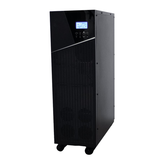
- Page 1 Endeavor 6K/10K On-line Tower UPS with Isolation Output Transformer User’s Manual...
- Page 2 Please read this manual before installing your Endeavor UPS, models ED6KTF, ED10KTF as it provides important information that should be followed during the installation and the maintenance of the UPS system allowing you to correctly set up your system for the maximum safety and performance.
-
Page 3: Table Of Contents
Table of Contents 1. SAFETY AND EMC INSTRUCTIONS ..........................1 1-1. T ............................1 RANSPORTATION AND TORAGE 1-2. P ..................................1 REPARATION 1-3. I ..................................1 NSTALLATION 1-4. C ..............................2 ONNECTION ARNINGS 1-5. O .................................. -
Page 4: Safety And Emc Instructions
1. Safety and EMC instructions Please carefully read the following user manual and the safety instructions before installing the unit or operating the unit! IMPORTANT SAFETY INSTRUCTIONS SAVE THESE INSTRUCTIONS! 1-1. Transportation and Storage Please transport the UPS system only in the original packaging to protect against shock and impact. The UPS must be stored in a ventilated and dry location. -
Page 5: Connection Warnings
1-4. Connection Warnings • In accordance with safety standard EN-IEC 62040-1, installation has to be provided with a Backfeed Protection system, as for example a contractor, which will prevent the appearance of voltage or dangerous energy in the input mains during a mains fault. There is no standard backfeed protection inside of the UPS. Please isolate the UPS before working according to below diagram. -
Page 6: Operation
1-5. Operation Do not disconnect the earth conductor cable on the UPS or the building wiring terminals since this would cancel the protective earth of the UPS system and of all connected loads. The UPS system features its own, internal current source (batteries). The UPS output may be electrically live even if the UPS system is not connected to the building wiring. -
Page 7: Installation And Operation
2. Installation and Operation This UPS series is ONLY intended to be installed in an indoor temperature controlled environment that is free of conductive contaminants. DO NOT operate the UPS in: extremely dusty and/or unclean areas, locations near heating devices, water or excessive humidity, or where the UPS is exposed to direct sunlight. -
Page 8: Rear Panel View
2-2. Rear Panel View Diagram 2: Non-isolated neutral terminal Diagram 1: Rear Panel Overlook Diagram 3: Input / Output Terminal RS-232 communication port USB communication port Emergency power off function connector (EPO connector) Option slot Charger fan Power stage fan Maintenance bypass switch 10. -
Page 9: Ups Installation
2-3. UPS Installation Installation and wiring must be performed in accordance with the local electric codes/regulations by qualified service personnel. Make sure the mains wire and breakers in the building are rated appropriately for the capacity of UPS to avoid the hazards of electric shock or fire. NOTE: Do not use the wall receptacle as the input power source for the UPS, as its rated current is less than the UPS’s maximum input current. - Page 10 NOTE 1: Make sure that the wires are connected tightly to the terminals. NOTE 2: There are two output terminals to meet customers’ requirements. NOTE 3: Please install the output breaker between the output terminal and the load. The breaker should be qualified with a leakage current protective function if necessary.
-
Page 11: Output Configuration
2-4. Output Configuration 1) 120V Outputs There are 2 sets of 120V outputs. Each set can carry half of the total UPS capacity. 240V 120V TO TO CUSTOMER 208V CUSTOMER LOAD LOAD 120V 120V 120V NOTE 1 120V 120V ISO TAP SELECTION OUTPUT~ INPUT~ 240V 208V... - Page 12 3) 240V Output A jumper wire must be connected between 0V and 120V as shown below. 240V 120V 208V TO CUSTOMER LOAD 240V NOTE 1 NOTE 2 240V 120V ISO TAP SELECTION OUTPUT~ INPUT~ 240V 208V 120V 120V Note 2: Full rated jumper must be installed Output wiring– 240V NOTE 1: ISO Tap Selection needs to be set to match the input voltage. Install a jumper between 0-208V or 0-240V. NOTE 2: A full rated jumper must be installed.
-
Page 13: Software Installation
5) 120V and 240V Output A jumper wire must be connected between 0V and 120V as shown below. 240V 120V 208V TO CUSTOMER LOAD 240V 120V 120V 120V NOTE 1 240V NOTE 2 120V 120V ISO TAP SELECTION OUTPUT~ INPUT~ 240V 208V 120V 120V Note 2: Full rated jumper must be installed Output wiring – 240V & 120V NOTE 1: ISO Tap Selection needs to be set to match the input voltage. -
Page 14: Operations
3. Operations 3-1. Button Operation Button Function Turn on the UPS: Press and hold the button for more than 0.5s to turn on the ON/Enter Button UPS. Enter Key: Press this button to confirm the selection in setting menu. ... - Page 15 LCD Panel: Display Function Backup time information Indicates battery discharge time. H: hours, M: minutes, S: seconds Fault information Indicates that a warning and/or a fault has occurred. Indicates the fault codes. The codes are listed in detail in section 3-9. Mute operation Indicates that the UPS alarm is disabled.
-
Page 16: Audible Alarm
Indicates the output is working. Battery information Indicates the Battery capacity by 0-25%, 26-50%, 51-75%, and 76-100%. Indicates the battery is not connected or bad. Indicates low battery warning and low battery voltage. Input & Battery voltage information Indicates the input voltage or frequency or battery voltage. VAC: Input voltage, VDC: battery voltage, Hz: input frequency 3-3. - Page 17 3) After a few seconds, the UPS will start up in the Battery mode. Turn on the connected equipment one device at a time. 3. Charge the batteries 1) The UPS will charge the batteries whenever the UPS is connected to an AC source and there is an acceptable AC voltage present.
- Page 18 8. Mute the buzzer 1) To mute the buzzer, press the “Mute” button on the front panel for at least 0.5s. If you press it again after the buzzer is muted, the buzzer will beep again. 2) Warning alarms can be muted. Please refer to section 3-3 for the details. 9.
-
Page 19: Abbreviation Meaning In Lcd Display
3-5. Abbreviation Meaning in LCD Display Abbreviation Display content Meaning Enable Disable Auto Battery Subtract Not allowed Allow Reserved OP.V Output voltage 3-6. LCD Setting There are three optional settings for the UPS. Refer to following diagram. Parameter 1 Parameter 1: There are 3 options that can be setup. - Page 20 01: Output voltage Interface Setting Parameter 3: Output voltage You may choose the following output voltages in parameter 3: 208VAC 220VAC 230VAC 240VAC (Default setting) NOTE: The UPS MUST be in the Bypass mode to make these changes. The UPS be turned OFF and then turned back ON to Save the changes.
-
Page 21: Operating Mode/Status Description
3-7. Operating Mode/Status Description Operating mode/status AC mode Description When the input voltage is within an acceptable range, the UPS will operate in the AC mode and charge the batteries. LCD display ECO mode Description When the input voltage is within voltage regulation range and ECO mode is enabled, UPS will bypass the input voltage to the connected load for energy saving. -
Page 22: Error Code
Battery Test Description When the UPS is in the AC mode, press the “Test” button for more than 0.5s. The buzzer will beep once and then the “Battery Test” will start. The line between the Input and inverter icons will blink to indicate the UPS is performing the “Battery Test’. -
Page 23: Warning Indicator
3-9. Warning Indicator Warning Icon (flashing) Buzzer Low Battery Warning Beeping every second Overload Beeping twice every second Battery disconnected Beeping every second Over charge Beeping every second EPO enable Beeping every second Fan failure/Over temperature Beeping every second Charger failure Beeping every second Input fuse open Beeping every second... -
Page 24: Trouble Shooting
4. Trouble Shooting If the UPS system does not operate correctly, please solve the problem by using the table below. Symptom Possible cause Remedy The LCD display is not illuminated even The input power is not Check if the input cable is firmly though the mains are normal. -
Page 25: Storage And Maintenance
5. Storage and Maintenance 5-1. Storage Before storing, charge the UPS for at least 24-hours. Store the UPS covered and upright in a dry, cool location. If the UPS is going to be out of service or stored for a prolonged period of time, the batteries must be recharged for at least 24-hours every 90 days. -
Page 26: Replacing The Battery
CAUTION: Replace batteries with the same number and type as originally installed in the UPS. These batteries have pressure operated vents. These UPSs contain sealed non-spillable maintenance-free lead acid batteries. Model ED6KTF ED10KTF Battery Quantity / Type 20 – 12V7.2Ah 20 –... -
Page 27: Battery Replacement Procedure
6-1. Battery Replacement Procedure (QUALIFIED SERVICE PERSONNEL ONLY) This UPS system does not have Hot-swappable batteries. The UPS system must be turned Off to perform the Battery Replacement Procedure. 1. Turn Off all the equipment that is connected to the UPS. 2. - Page 28 10. Looking from the rear of the UPS on the right-hand side (FIG. 2), disconnect the battery positive (Red) wire. Place a piece of electrical tape over the end of battery positive (Red) wire. 11. Looking from the rear of the UPS on the right-hand side disconnect the battery negative (Black) wire. Place a piece of electrical tape over the end of battery negative (Black) wire.
- Page 29 14. Remove the battery retaining bracket retaining screws and the battery retaining brackets on the right hand side (FIG. 4). FIG. 4 15. Remove the batteries from the top row and set aside (FIG. 5). FIG. 5...
- Page 30 16. Remove the battery retaining bracket from the second row of batteries and set aside (FIG. 6). FIG. 5 17. Remove the batteries from the second row and set aside (FIG. 6). FIG. 6...
- Page 31 18. Remove both sets of batteries from the third row and set aside (FIG. 7). FIG. 7 19. Install both sets of the new batteries on the third row (FIG. 8). NOTE: The battery terminals MUST be on the bottom side. FIG.
- Page 32 20. Install the new batteries on the second row (FIG. 9). NOTE: The battery terminals MUST be on the top side. FIG. 9 21. Install the battery retaining bracket on the second row of batteries (FIG. 10) FIG. 10...
- Page 33 22. Install the new batteries on the top row (FIG. 11). NOTE: The battery terminals MUST be on the bottom side. FIG. 11 23. Re-install the battery-retaining brackets with the retaining screws on the right hand side (FIG. 12). FIG. 12...
- Page 34 24. Observer polarity. Re-install all of the battery jumper wires on the left hand side (FIG. 13). FIG. 13 25. Observer polarity. Re-install all of the battery jumper wires on the right hand side (FIG. 14). 26. Remove the piece of electrical tape from the end of battery negative (Black) wire. 27.
- Page 35 30. Re-install the side panels and the retaining screws (FIG. 15). 31. Re-install the top cover and the retaining screws. FIG. 15 32. Reconnect all of the communications and network cables. NOTE: If you are using an External Battery Pack, reconnect the all of the battery cables to the UPS and the Battery Pack(s) rear panels.
-
Page 36: Specifications
7. Specifications MODEL ED6KTF ED10KTF CAPACITY* 6000 VA / 6000 W 10000 VA / 10000 W INPUT 110 VAC (L-N) ± 3 % at 0-60% Load Low Line Loss 176 VAC (L-N) ± 3 % at 60%-100% Load Voltage Low Line Comeback... -
Page 37: Limited Product Warranty
8. Limited Product Warranty Para Systems, Inc. (Para Systems) warrants this equipment, when properly applied and operated within specified conditions, against faulty materials or workmanship for a period of three (3) years from the date of purchase. For equipment sites within the United States and Canada, this warranty covers depot repair or replacement of defective equipment at the discretion of Para Systems. -
Page 38: A1. Declaration Of Conformity
61000-4-5: level 4, IEC/EN 61000-4-6: level 3, IEC/EN 61000-4-8: level 4, IEC/EN 62040-1-1, IEC/EN 62040-2, IEEE C62.41 Category A1, FCC PART15 CLASS A Manufacturer’s Name: Para Systems, Inc. (MINUTEMAN UPS) Manufacturer’s Address: 1455 LeMay Drive, Carrollton, Texas 75007 USA Type of Equipment:... - Page 39 Para Systems, Inc. 1455 Lemay Dr. Carrollton, TX 75007 Phone: 1-972-446-7363 Fax: 1-972-446-9011 Internet: minutemanups.com UPS Sizing: sizemyups.com PN: 34000535 R2...
Need help?
Do you have a question about the ED6KTF and is the answer not in the manual?
Questions and answers