
Related Manuals for Classic Exhibits VISIONARY DESIGNS VK-3006


Summary of Contents for Classic Exhibits VISIONARY DESIGNS VK-3006
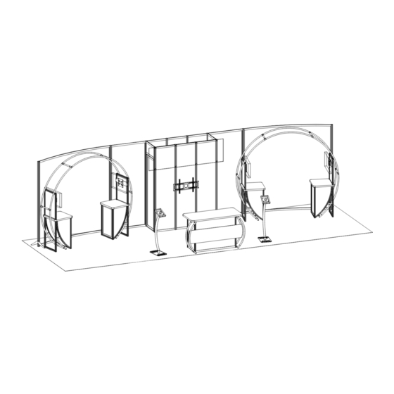
- Page 1 © 2017 Order #XXXXX VK-3006 - 10’ x 30’ Inline Display 10’ 30’ Plan View SETUP INSTRUCTIONS If you would like to tell us about your experience with your setup instructions please email us at info@classicexhibits.com...
- Page 2 © 2017 Order #XXXXX General Information General Setup Instructions - Read entire setup instruction manual prior to WARNING unpacking parts and pieces. - The setup instructions are created specifically for this configuration. - Setup instructions are laid out sequentially in steps, including exploded views with detailed explanation for assembly.
- Page 3 © 2017 Order #XXXXX Closet Assembly Item Qty. Description 96”h S44 Vertical Extrusion w/ Door Stop 5,6,7 1,1,1 96”h S44 Vertical Extrusion 8,9,10 1,1,1 96”h S44 Vertical Extrusion Top View 96”h S44 Vertical Extrusion w/ Door Hinge Velcro 12/12A 22.126”w Z45 Horizontal Extrusion Top View 13/13A 22.5”w Z45 Horizontal Extrusion...
- Page 4 © 2017 Order #XXXXX Closet Attachments Steps: 1) Install Door to Vertical [11]. See Door Attachment detail. 2) Attach Monitor Mount to Verticals [9,10]. Monitor Mount Attachment detail. 3) Connect Header Graphic to Verticals [8,9,10,11] using screw caps. See Header Attachment detail.
- Page 5 © 2017 Order #XXXXX Left Backwall Assembly Item Qty. Description Boomerang Foot 96”h S44 Vertical Extrusion 96”h S44 Vertical Extrusion 17/17A 40”w Z45 Horizontal Extrusion 18/18A 96” Z45 curved Horizontal Extrusion 92.4”h PR37 Vertical Extrusion Top View Velcro Velcro Steps: PR37 PR37 1) Connect PR37 to verticals [2,16], as shown.
- Page 6 © 2017 Order #XXXXX Right Backwall Assembly Item Qty. Description Boomerang Foot 96”h S44 Vertical Extrusion 96”h S44 Vertical Extrusion 20/20A 40”w Z45 Horizontal Extrusion 21/21A 96” Z45 curved Horizontal Extrusion 92.4”h PR37 Vertical Extrusion Top View Steps: Velcro Velcro 1) Connect PR37 to verticals [2A,19], as shown.
-
Page 7: Push Button
© 2017 Order #XXXXX Left Aero Ring Assembly Using Your Setup Instructions The Aero Overhead Sign Setup Instructions are created specifically for your configuration. They include an exploded view of the frame which is sequentially numbered. We encourage you to study the instructions before attempting to assemble your exhibit. - Page 8 © 2017 Order #XXXXX Right Aero Ring Assembly Using Your Setup Instructions The Aero Overhead Sign Setup Instructions are created specifically for your configuration. They include an exploded view of the frame which is sequentially numbered. We encourage you to study the instructions before attempting to assemble your exhibit.
- Page 9 © 2017 Order #XXXXX Workstation Assembly Monitor Mount Attachment Item Qty. Description Door Attachment 66”h S40 Vertical Extrusion connectors 66”h S40 Vertical Extrusion Slide pin into Door hinge attached 36”h S40 Vertical Extrusion w/ Door Hinge Hinge to vertical. 36”h S40 Vertical Extrusion w/ Door Stop Slide door 40.975”...
- Page 10 © 2017 Order #XXXXX Workstation to Aero Ring Connection Steps: 1) Slide assembled Kiosks over Aero frame. 2) Connect Aero Frame to Kiosks using custom bracket. Custom Bracket Connection detail. Repeat steps 1 & 2 for other Aero Frame. When assembled QTY 2 Custom Bracket Connection Slide V4 connectors into groove of...
-
Page 11: Back View
© 2017 Order #XXXXX Reception Counter - Assembly Steps: Item Qty. Description 1) Connect lower Horizontals [5,6] between Verticals [1,2,3,4]. 37.5”h Vertical Extrusion 2) Attach Vertical [7] to lower Horizontal [6]. 37.5”h Vertical Extrusion 3) Slide Infills between Verticals [1,2] [2,3] and [3,4]. 37.5”h Vertical Extrusion 4) Connect Horizontal [6A] between Verticals [2,3]. - Page 12 © 2017 Order #XXXXX Reception Counter - Aero Frame Using Your Setup Instructions The Aero Overhead Sign Setup Instructions are created specifically for your configuration. They include an exploded view of the frame which is sequentially numbered. We encourage you to study the instructions before attempting to assemble your exhibit.
-
Page 13: Completed Assembly
© 2017 Order #XXXXX Reception Counter - Attachments Steps: 1) Slide Aero Frame assemblies into the groove of front Verticals [2] & [3]. 2) Attach front Sintra graphic to Verticals [2,3], using Velcro. 3) Place Counter Top on top of assembled Base. Counter Top Attachment detail. - Page 14 © 2017 Order #XXXXX iPad Kiosk Steps: 1) Attach base to curved stand, using bolts. 2) Attach square plate to stand, using bolts. NOTE: Square plate must rotate to left and right before installing clamshell. 3) Attach clamshell to square plate using hex nuts. 4) Insert iPad and feed wire through hole as shown in detail.
Need help?
Do you have a question about the VISIONARY DESIGNS VK-3006 and is the answer not in the manual?
Questions and answers