
Related Manuals for Classic Exhibits visionary VK-2098


Summary of Contents for Classic Exhibits visionary VK-2098
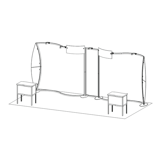
- Page 1 Step 1 Order #XXXXX - Magellan MOR VK-2098 - General Layout 866.652.2100 10’ Plan View 20’ WHEN DISASSEMBLING ALUMINUM EXTRUSION, TIGHTEN ALL SETSCREWS AND LOCKS TO PREVENT LOSS DURING SHIPPING © 2009 w w w . c l a s s i c e x h i b i t s . c o m Page 1 of 4...
- Page 2 Step 2 Order #XXXXX - General Information 866.652.2100 Using Your Setup Instructions The Visionary Designs Setup Instructions are created specifically for your Detail A configuration. They are laid out sequentially, including an exploded view of the entire display, and then a logical series of detailed steps to assemble the main structure and components.
- Page 3 Step 1 Order #XXXXX - Backwall Assembly 866.652.2100 Part Number Description Base Plate Pressure Screw 48.115” Lower Curved Extrusion Note: Extrusions 5/5a and 4/4a 48.115” Upper Curved Extrusion must stay assembled when shipping. 47”h Lower Vertical Extrusion 47”h Upper Vertical Extrusion Velcro attched to LOWER 6a/6b 52.476”...
- Page 4 Step 2 Order #XXXXX - Backwall Assembly (Cont’d) 866.652.2100 Part Number Description Base Plate 47”h Lower Vertical Extrusion 47”h Corner Extrusion 47”h Upper Vertical Extrusion Connection Velcro attched to LOWER 47”h Corner Extrusion back of extrusion bar Note: Extrusions 8/8a and 9/9 48.115”...
- Page 5 Step 3 Order #XXXXX - Light, Header and Wing Attachment 866.652.2100 Light Connection Attach Lights to Backwall where desired and tighten in place. Attach Header Signs to Wing Attachment Frame using Screw Caps. Slide A10 Clamp into groove of square extrusion. When desired location is found, tighten set screw to secure.
-
Page 6: Pedestal Assembly
Step 4 Order #XXXXX - Pedestal Assembly 866.652.2100 Item Qty. Description 37.50”h Vertical Extrusion 37.50”h Vertical Extrusion Door Stop 37.50”h Vertical Extrusion 37.50”h Vertical Extrusion Horizontal Extrusion w/ Lip Horizontal Extrusion Curved Horizontal Extrusion Steps 1) Connect lower horizontal extrusions [19 and 21] between vertical extrusions [15, 16, 17 and 18] as shown. 2) Place inserts and attach door where indicated. - Page 7 Order #XXXXX - Case Packing Instruction - Case 1 of 4 866.652.2100 Backwall Components Header Graphic Graphics 2 - Base Plates Lights and Setups Hardware 2 - Set of Wings Level 1 Level 2 Level 3 Slip Sheet WHEN DISASSEMBLING ALUMINUM EXTRUSION, TIGHTEN ALL SETSCREWS AND LOCKS TO PREVENT LOSS DURING SHIPPING ©...
- Page 8 Order #XXXXX - Case Packing Instruction - Case 2 of 4 866.652.2100 Backwall Components cont’d 2 - Base Plates Level 1 Level 2 WHEN DISASSEMBLING ALUMINUM EXTRUSION, TIGHTEN ALL SETSCREWS AND LOCKS TO PREVENT LOSS DURING SHIPPING © 2009 w w w . c l a s s i c e x h i b i t s . c o m...
- Page 9 Order #XXXXX - Case Packing Instruction - Case 3 of 4 866.652.2100 MOD-1235 Components Door Stop 3A - Door Stop Internal Shelf Assembled Assembled Pedestal Side Pedestal Door Pedestal Side Front Insert Counter Top Level 5 Level 4 Level 2 Level 3 Level 1 WHEN DISASSEMBLING ALUMINUM EXTRUSION, TIGHTEN ALL...
- Page 10 Order #XXXXX - Case Packing Instruction - Case 4 of 4 866.652.2100 MOD-1235 Components Door Stop 3A - Door Stop Internal Shelf Assembled Assembled Pedestal Side Pedestal Door Pedestal Side Front Insert Counter Top Level 5 Level 4 Level 2 Level 3 Level 1 WHEN DISASSEMBLING ALUMINUM EXTRUSION, TIGHTEN ALL...
Need help?
Do you have a question about the visionary VK-2098 and is the answer not in the manual?
Questions and answers