
Related Manuals for Classic Exhibits VISIONARY DESIGNS VK-1214


Summary of Contents for Classic Exhibits VISIONARY DESIGNS VK-1214
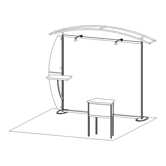
- Page 1 Step 1 Order #xxxxx - Sacagawea - VK-1214 - General Layout 866.652.2100 10’ Plan View 10’ WHEN DISASSEMBLING ALUMINUM EXTRUSION, TIGHTEN ALL SETSCREWS AND LOCKS TO PREVENT LOSS DURING SHIPPING © 2009 w w w . c l a s s i c e x h i b i t s . c o m Page 1 of 4...
- Page 2 Step 2 Order #xxxxx - Sacagawea - General Information 866.652.2100 Using Your Setup Instructions The Visionary Designs Setup Instructions are created specifically for your Detail A configuration. They are laid out sequentially, including an exploded view of the entire display, and then a logical series of detailed steps to assemble the main structure and components.
- Page 3 Step 1 Order #xxxxx - Sacagawea - Backwall Assembly 866.652.2100 Steps: Item Qty. Description 1) Attach vertical extrusions [2] to base plates [1]. Base Plate 2) Attach upper vertical extrusions [3a and 3] to lower extrusions [2a and 2] 42”h Lower Square Vertical Extrusion using connection bar [a].
- Page 4 Step 2 Order #xxxxx - Sacagawea - Counter and Wing Attachment 866.652.2100 Steps: Item Qty. Description 1) Connect horizontal extrusion [11] to curved extrusion [10]. 30.2” Curved Extrusion 2) attach assembled counter support [10/11] to vertical where indicated. 12.184”w Horizontal Extrusion 3) Attach flange plate [11a] to top of curved extrusion [10] as shown.
- Page 5 Step 3 Order #xxxxx - Sacagawea - Canopy Assembly 866.652.2100 Steps: 1) Connect canopy pieces together as shown. 2) Apply pillow case graphic to assembled canopy Using Your Setup Instructions The Aero Overhead Sign Setup Instructions are created specifi cally for your confi guration. They include an exploded view of the frame which is sequentially numbered.
- Page 6 Step 4 Order #xxxxx - Sacagawea - MOD-1243 - Pedestal Assembly 866.652.2100 Part Number Description 38”h Vertical Extrusion 13/13a 12”w Horizontal Extrusion 25”w Horizontal Extrusion Steps (Cont’d): 3) Place shelf atop lip of extrusions. Steps 1) Attach horizontal extrusions [13 and 13a] between vertical 4) Set counter top atop assembled base.
- Page 7 Order #xxxxx - Case Packing Instruction - Case 1 of 2 866.652.2100 (1) Backwall Components Backwall Counter Canopy Pieces Support Setup Hardware Counter and Lights Wing Panels Graphics Base Plates Level 2 Level 3 Level 1 Level 4 Level 5 WHEN DISASSEMBLING ALUMINUM EXTRUSION, TIGHTEN ALL SETSCREWS AND LOCKS TO PREVENT LOSS DURING SHIPPING ©...
- Page 8 Order #xxxxx - Case Packing Instruction - Case 2 of 2 866.652.2100 (2) Pedestal Components Front Insert Assembled Assembled Pedestal Pedestal Side Side Counter Top Internal Shelf Level 3 Level 4 Level 2 Level 1 WHEN DISASSEMBLING ALUMINUM EXTRUSION, TIGHTEN ALL SETSCREWS AND LOCKS TO PREVENT LOSS DURING SHIPPING ©...
Need help?
Do you have a question about the VISIONARY DESIGNS VK-1214 and is the answer not in the manual?
Questions and answers