
Related Manuals for CIS VISION:elite VCC-FM60FV19CL


Summary of Contents for CIS VISION:elite VCC-FM60FV19CL
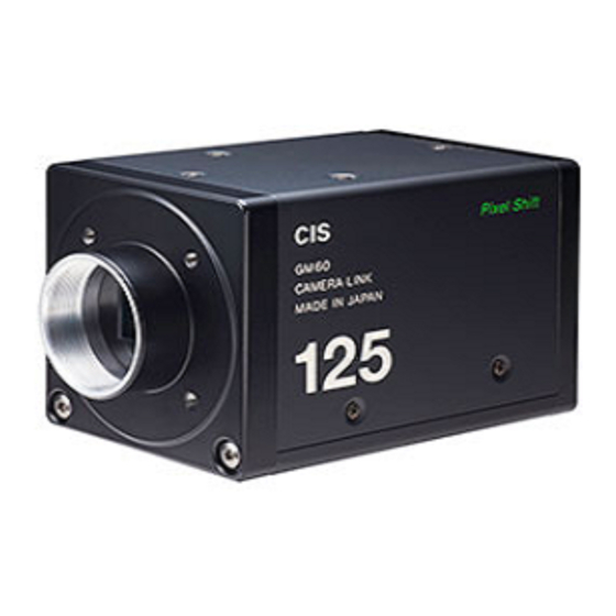
- Page 1 VCC-FM60FV19CL Rev. 900-714-31-00 English 45M Ultra High Resolution Color Camera Link (RAW) VCC-FM60FV19CL Product Specification & Operational Manual CIS Corporation ©2011 CIS Corporation. All rights reserved.
-
Page 2: Table Of Contents
12. Image Synthesis ········································································································ 23 13. CCD Optical Axis Accuracy ···························································································· 25 14. Dimensions ·············································································································· 26 15. Cases for Indemnity (Limited Warranty) ··········································································· 27 16. CCD Pixel Defect ········································································································ 27 17. Product Support ········································································································ 27 ©2011 CIS Corporation. All rights reserved. -
Page 3: Scope Of Application
AC leaks from the connected devices may cause damages or destroy the camera. Do not apply excessive voltage. (Use only the specified voltage.) Unstable or improper power supply voltage may cause damages or malfunction of the camera. ©2011 CIS Corporation. All rights reserved. - Page 4 Therefore, differences between right screen and left screen could be seen depending on the usage conditions (shooting conditions /temeperature conditions and so on). CIS trys its best to adjust this differences but please be noted it would not be perfect. Voltage Rising Time [ ms ]...
-
Page 5: Product Outline
※ Please ask us for the details on image synthesis software. Verified Frame Grabber Board □ TB-6S-LX150T-GB-R (Tokyo Electron Device LTD). ※ Please ask Tokyo Electron Device Ltd for the details on the frame grabber board. ©2011 CIS Corporation. All rights reserved. -
Page 6: Specification
(Refer to overall dimension drawing) (13) Optical axis accuracy Refer to drawing for CCD Optical Axis Accuracy. (14) Gain variable range 0~+12dB (Analog Gain over 0dB~+6dB, Digital Gain 0dB~+6dB) (15) 1/15s (OFF) ~1/30000s Shutter speed variable (16) range ©2011 CIS Corporation. All rights reserved. - Page 7 RH 20~80% with no condensation. Humidity -25℃~+60℃ Temperature Storage Environment (22) Humidity RH 20~80% with no condensation. ※ In this Specification, we describe pixel shifting technology as “SOPT: Spatial Offsetting Pickup Technique”. ©2011 CIS Corporation. All rights reserved.
-
Page 8: Camera Output Signal Specification
: Under 08h for both horizontal and vertical. (Conditions: Gain 0dB) Leval differences At Digital 8bit : Under 03h (Conditions: Gain 0dB) between right and left ※ 2 secounds shall be waited after turning on power to get proper camera operation. ©2011 CIS Corporation. All rights reserved. -
Page 9: Ccd Spectral Response (Representative Value)
※ Lens charcteristics and luminous source charcteristics are not considered. 4.4. Video Output Format ・ 2-Taps Output ・ Area of interest Width : 2448 Height : 2058 Offset X : 0 Offset Y : 12 ・ Bayer Pattern RGGB ©2011 CIS Corporation. All rights reserved. -
Page 10: Function Settings
009&010 0~2078: 1/15s(OFF)~1/36058s ※Set the data of address 002 to 016. Manual Shutter Control Address 009 MSB and address 010 LSB makes total 16bit. Shutter Speed = (2078 - (009&010))×32.07μs+27.73μs Max Data = 2078 ©2011 CIS Corporation. All rights reserved. - Page 11 Light access is recognized as a trigger. There is no need to prepare a pulse trigger with data values. 45M Mode SOPT Mode 3CCD Mode Standby OFF External Trigger Standby SOPT Standby Software Trigger Standby ©2011 CIS Corporation. All rights reserved.
- Page 12 ※ In this Specification, we describe pixel shifting technology as “SOPT: Spatial Offsetting Pickup Technique”. ※ The data set with 2 Byte shall be set with High Byte first, then set with Low Byte. The camera rewrites the internal resister when receiving Low Byte. ©2011 CIS Corporation. All rights reserved.
-
Page 13: External Connector Pin Assignment
6.2. 26 pins Camera Link Connector 12226-1100-00 PL (SUMITOMO 3M) Pin No. Pin No. 名 称 XCLK- XCLK+ SerTC+ SerTC- SerTFG- SerTFG+ CC1- (Trigger IN -) CC1+ (Trigger IN +) NA (CC2+) NA (CC2-) NA (CC3-) NA (CC3+) NA (CC4+) NA (CC4-) ©2011 CIS Corporation. All rights reserved. -
Page 14: Timing Chart
2Tap Output 7.2. Full Frame Scan Mode Video Output 2058 H 21 H 2058 H (CCD Read Out Signal) 2075 2076 2077 2078 2079 LVAL Output DVAL Output FVAL Output 12 H Total = 2079H ©2011 CIS Corporation. All rights reserved. -
Page 15: Fixed Trigger Shutter Mode
Exposure Time Standard Trigger Mode Trigger Invalid Trigger IN (Exposure Time) Exposure Output (F) (B) Exposure Time ( Register Set Value ) Exposure Time (Register Set Value ) Video Output (F ) (B) DVAL Output ©2011 CIS Corporation. All rights reserved. -
Page 16: Pulse Width Trigger Shutter Mode
Exposure Output (Exposure Time ) (B) Exposure Time Exposure Time Exposure Time (B) (Pulse Width ) (Pulse Width ) ( Pulse Width ) (Video Output ( C )) (D ) Video Output DVAL Output ©2011 CIS Corporation. All rights reserved. -
Page 17: Partial Scan Mode Details
1219 H 26 fps ・ ・ ・ ・ 1026 H 1391 H 22 fps ・ ・ ・ ・ 1200 H 1507 H 21 fps ・ ・ ・ ・ 2058 H 2079 H 15 fps ©2011 CIS Corporation. All rights reserved. -
Page 18: Remote Communication Function
To save the data into EEPROM, please refer to Section 5. Function Settings. C is the code to send the data back from the camera. Note: Do not set code C when sending the data from PC side. ©2011 CIS Corporation. All rights reserved. -
Page 19: Initial Settings
Partial Scan Total Line 021&022 2078: Read Only Baud Rate 9600bps Frame ID ON/OFF SOPT Mode 45M Mode SOPT Standby Standby OFF ※ In this Specification, we describe pixel shifting technology as “SOPT: Spatial Offsetting Pickup Technique”. ©2011 CIS Corporation. All rights reserved. -
Page 20: Sopt Control
Software Trigger Mode Standby Send Control Command 000000W063002 Software Trigger Output Send Control Command Camera output 000000W061000 45M Mode 9pcs. 3CCD Mode 4pcs. Capturing Images Image synthesis Repeat ? Cancel Standby Send Control Command 000000W063000 Completion ©2011 CIS Corporation. All rights reserved. -
Page 21: External Trigger Control Sequence
000000W062000 000000W062001 External Trigger Mode Standby Send Control Command 000000W063001 External Trigger Output Camera Output 45M Mode 9pcs 3CCD Mode 4pcs Capturing Images Image Synthesis Repeat ? Cancel Standby Send Control Command 000000W063000 Completion ©2011 CIS Corporation. All rights reserved. -
Page 22: To Operate Sopt With Software Trigger (45M Mode)
(1) With 1 trigger input, 9 images can be output at 45M mode and 4 images can be output at 5M 3CCD mode. (2) Partial scan mode can not be used at SOPT Mode. (3) Pulse width trigger mode can not be used at SOPT Mode. Shutter values should be set at the address 002. ©2011 CIS Corporation. All rights reserved. -
Page 23: Image Synthesis
0, 1 0, 1 1, 1 1, 1 0 ,1 1, 1 1, 1 0, 1 0 ,1 1, 1 1, 1 0, 1 1st Image 2nd Image 3rd Image 4th Image 2448 pixels R,Gr,B,Gb ©2011 CIS Corporation. All rights reserved. - Page 24 Frame ID Data (8bit) : SOPT OFF Image ・・・ 00(Hex) SOPT ON Image ・・・ 01(Hex) ~ 09(Hex) 45M Mode 01(Hex) ~ 04(Hex) 3CCD Mode Address : 060 Data : 0 ・・・ Frame ID OFF 1 ・・・ Frame ID ON ©2011 CIS Corporation. All rights reserved.
-
Page 25: Ccd Optical Axis Accuracy
Inclination of the effective pixels “Theta” Datum Plane A to the datum plane A is ?? ±1.0° *)Dimensions from datum plane A to the center of the lens mount. 910-018-00-00 (Unit:mm) ©2011 CIS Corporation. All rights reserved. -
Page 26: Dimensions
VCC-FM60FV19CL Rev. 900-714-31-00 14. Dimensions ©2011 CIS Corporation. All rights reserved. -
Page 27: Cases For Indemnity (Limited Warranty)
On very rare occasions, however, CCD pixel defects might be noted with time of usage of the products. Cause of the CCD pixel defects is the characteristic phenomenon of CCD itself and CIS is exempted from taking any responsibilities for them. Should you have any questions on CCD pixel defects compensation, please contact us.
Need help?
Do you have a question about the VISION:elite VCC-FM60FV19CL and is the answer not in the manual?
Questions and answers