
Related Manuals for CIS VISION:analog VCC-G20X30T1


Summary of Contents for CIS VISION:analog VCC-G20X30T1
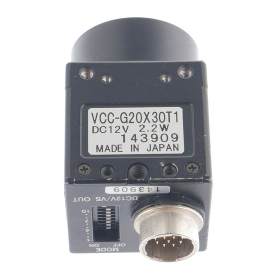
- Page 1 VCC-G20X30T1 Rev. 900-557-32-00 29mm Cubic XGA Analog B/W Camera VCC-G20X30T1 Product Specification & Operational Manual CIS Corporation ©2009 CIS Corporation. All rights reserved.
-
Page 2: Table Of Contents
8.6. External trigger operation timing by pulse width setup (SYNC Reset type) ......... 16 8.7. External trigger operation timing by pulse width setup (SYNC Non-Reset type) ......17 Cases for Indemnity (Limited Warranty) ..................18 10. CCD Pixel Defect ........................18 11. Product Support ........................18 ©2009 CIS Corporation. All rights reserved. -
Page 3: Scope Of Application
Especially in INT/EXT sync signal settings, improper connection may cause damages to the camera and the connected devices. At least 5 seconds shall be waited to reboot the camera. In case of abnormal operation, contact the distributor from whom you purchased the product. ©2009 CIS Corporation. All rights reserved. -
Page 4: Product Outline
1/4 Partial Scan Mode □ 29mm Cubic in size Its small size, 29mm cubic, and light weight, 44g, makes it a best match for use in embedded systems for image calibration and microscopic applications. ©2009 CIS Corporation. All rights reserved. -
Page 5: Specification
30.0 MHz Analog output 1.0V(p-p) Sync. negative, 75Ω unbalanced, DC connect White clip level 820 ± 50mVp-p Video output signal Setup level 25 ± 15mVp-p Sync level 290 ± 30mVp-p DC level 500 ± 100mV ©2009 CIS Corporation. All rights reserved. - Page 6 Refer to overall dimension drawing (Clause 7) 29mm(H) x 29mm(W) x 29mm(D) (excluding protruding part) Mass Lens Mount C Mount Flange Back Flange focal length fixed Optical axis accuracy Within φ0.4 from the center ©2009 CIS Corporation. All rights reserved.
-
Page 7: Durability
This device complies with Part 15 of the FCC Rules. Operation is subject to the following two conditions: (1) this device may not cause harmful interference, and (2) this device must accept any interference received, including interference that may cause undesired operation. ©2009 CIS Corporation. All rights reserved. -
Page 8: Ccd Spectral Response (Representative Value)
VCC-G20X30T1 Rev. 900-557-32-00 4.4. CCD Spectral Response (Representative Value) 4.5. Optical Black Layout Pin No.1 Optical Black Effective Image Area Pin No.9 Signal Output Top View H:1034 , V:779 ©2009 CIS Corporation. All rights reserved. -
Page 9: External Connector Pin Assignment
Normal Mode / Restart-Reset Mode ● MODE0 Trigger Shutter Mode ● GAIN ◇Fix 0dB / Manual Gain 0~12dB ● PARTIAL ◇Partial Scan ON/OFF ● IN/OUT ◇HD/VD Input, Output ON: Input ● indicates initial setting position. ● ©2009 CIS Corporation. All rights reserved. - Page 10 Rear Switch for HD/VD Input Output SW10 HD/VD Output Valid at normal operation HD/VD Input Valid at normal operation, long time exposure operation, and trigger shutter operation (non-reset) HD Input Trigger shutter operation (reset) ©2009 CIS Corporation. All rights reserved.
-
Page 11: Function
Exposure time can be set by trigger pulse width (Switch 6 ON) or fixed switch setting (Switch 6 OFF). ● Note; Do not input another trigger before completion of video signal output for prior trigger. ©2009 CIS Corporation. All rights reserved. - Page 12 Start and completion of exposure time does not correspond to HD synchronization signals. Trigger input Discharge Read out Exposure time 3.3us 6.8us External HD/VD Input Phase With full frame scan, the following input condition applies only to the first field. External VD External HD 0±5us ©2009 CIS Corporation. All rights reserved.
-
Page 13: Dimensions
VCC-G20X30T1 Rev. 900-557-32-00 7. Dimensions ©2009 CIS Corporation. All rights reserved. -
Page 14: Timing Chart
Camera HD CCD output Black Black Transmit Read out signal Invalid pixel Video output signal 768H Vertical blanking Video output active term ( 1185us ) WEN output signal ※ ※ WEN cann't use Normal mode. ©2009 CIS Corporation. All rights reserved. -
Page 15: Vertical Synchronous Timing Of Binning Scan
Read out signal Video output signal Vertical blanking term Video output active term 1/2 Partial 33H 1/2 Partial 348H 1/4 Partial 38H 1/4 Partial 136H WEN output signal ※ WEN cann't use Normal mode. ©2009 CIS Corporation. All rights reserved. -
Page 16: Long Time Exposure Mode Timing (Restart Reset Operation)
When used as camera slave, HD input is valid but VD input is invalid. ※3 When used as camera master, single VD, CSYNC signal will be output with setting SW 10 at rear to OFF. ©2009 CIS Corporation. All rights reserved. -
Page 17: External Trigger Operation Timing By Pulse Width Setup (Sync Non-Reset Type)
Exposure time = Trigger Pulse Width + 3.5μs External HD/VD signals must be input because only camera slave side is operated. ※3 Waiting time from trigger input down edge to external VD input down edge should be set within 10μs~35ms. ※4 ©2009 CIS Corporation. All rights reserved. -
Page 18: Cases For Indemnity (Limited Warranty)
After delivery, on the rare occasion, CCD pixel defects might be noted with time of usage of the products. The cause of the CCD pixel defects is the characteristic phenomenon of CCD itself and CIS shall be exempted from taking responsibility on it.
Need help?
Do you have a question about the VISION:analog VCC-G20X30T1 and is the answer not in the manual?
Questions and answers