Table of Contents
Advertisement
Quick Links
★ Please read and follow all warnings, precautions and instructions before
C030685
installation and use.
★ Periodic checks of the opener are required to ensure safe operation.
★ Save this manual.
Warning: A photocell sensor is included in the package. The photocell must be
installed with the gate opener for SAFETY PROTECTION. The jumper wire between
the PHO & COM terminals (NO.14 & NO.15) MUST BE REMOVED before installing the
photocell.
C030685
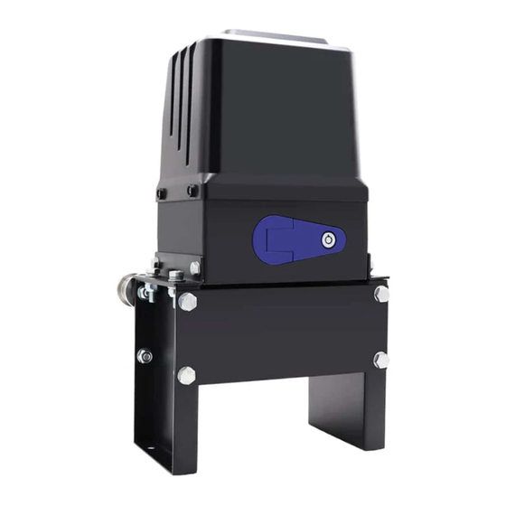
Sliding Gate Opener
User's Manual
Model:
CK2500
TOPENS Website
www.topens.com
Email: support@topens.com
VER 23a
VER 23b
Advertisement
Table of Contents

Subscribe to Our Youtube Channel
Related Manuals for Topens CK2500


Summary of Contents for Topens CK2500
- Page 1 Sliding Gate Opener User’s Manual Model: CK2500 TOPENS Website www.topens.com Email: support@topens.com ★ Please read and follow all warnings, precautions and instructions before C030685 VER 23a installation and use. ★ Periodic checks of the opener are required to ensure safe operation.
- Page 2 Visit: www.topens.com Please record the product model, your email address etc. in the spaces provided below. Refer to this list when contacting TOPENS for technical service or assistance with your automatic gate opener. Where did you purchase? (Amazon.com; Amazon.ca: Amazon.co.uk, Amazon.de; Other, Please...
-
Page 3: Table Of Contents
Preparation for Installation........................... 2 Parts List ..............................4 Accessories Parts (Included in some models, refers to the actual package) ..........4 Optional Accessories Parts List (Available at TOPENS Store) ..............5 Replacement Parts ............................5 Technical Specifications & Features ......................6 Installation Overview ........................... -
Page 4: Check Your Gate Before Installation
Thank you for purchasing our sliding gate opener. We are sure that the products will be greatly satisfying as soon as you start to use it. The product is supplied with a user’s manual which encloses installation and safety precautions. These should be read carefully before installation and operation as they provide important information about safety, installation, operation and maintenance. -
Page 5: Preparation For Installation
• Position at least one visible indication device, and fix a Warning sign to the structure. • The factory declines all responsibility with respect to the automation safety and correct operation when other supplier’s components are used. • Only use original parts for any maintenance or repair operation. •... - Page 6 In sake of safety, a positive stop must be mounted on the two end of ground track.
-
Page 7: Parts List
Parts List Accessories Parts (Included in some models, refers to the actual package) -
Page 8: Optional Accessories Parts List (Available At Topens Store)
JD110VY Warning Light Chain Exit Wand Replacement Parts ACPYMJ11A-JCQ PYMJ-CKG Limit Switch Magnet Assembly (N Control Board (120V) pole & S pole) WARNING: Changes or modifications not expressly specified by this user manual, TOPENS could void the warranty of this equipment. -
Page 9: Technical Specifications & Features
Technical Specifications & Features Specifications CK2500 Power input: 110~120V/60Hz Motor voltage: 120VAC Rated power: 1000W Gate moving speed: 20 cm/s (8 in/s) Max gate weight: 2600kg (5700lbs) -20 ~ +50 (0°F to 120°F) Environmental conditions: Protection class: IP44 •Reverse in case of photocell beam obstruction... -
Page 10: Installation Overview
Installation Overview Installation of the Opener Caution: *Be sure that the opener is installed in a level and paralleled position . Improper installation could result in property damage , severe injury, and/or death. * Before starting installation, ensure that there is no point of friction during the entire movement of the gate and there is no danger of derailment. -
Page 11: Manual Operation
cables before pour concrete. Remember that cable conduits have to pass through the hole on the base. 4. Pour concrete and before it starts to harden, check that it is parallel to the gate leaf and perfectly level. 5. Mark the position of four expansion anchors according to the position of mounting hole on the base plate. Double check the marking, move the base plate and drill the 4 holes using a 14mm (9/16”) masonry bit. -
Page 12: Installation Of The Magnets
6). The chain brackets must be mounted to the same height as the chain on the idler wheels. 7). Make sure there is 1” distance at least between the wheel cover and the gate after you position the base plate. Installation of the Magnets Before install limit switch, make sure the gate opener is put in manual operation. -
Page 13: Connecting Of Power Supply
desired close position when the close limit switch approaches it. Push the gate fully open by hand. Locate and install the magnet bracket so that the opener will stop at the desired open position when the open limit switch approaches it. The magnet component with S pole must be installed at left side and the magnet component with N pole mu st be installed at right side from the view inside of property. - Page 14 terminal to the “15” terminal. 5. Reflection Photocell Sensor (optional) The “AC10-25V/DC12-30V” terminals of the reflection photocell sensor should be connected to the “12” and “13” terminals, no matter the polarity. The “NC” terminal should be connected to the “14” terminal. The “COM”...
-
Page 15: Setting Of The Control Board
6. Push Button (Optional) The push button should be wired to the “15” and “16” terminals. The gate opener works alternately by pushing the button (open-stop-close-stop-open). 7. Exit Wand (Optional) First insert the Adapter BOARD into the CONTROL BOARD, and then connect the wand to the control board refers to following instruction. -
Page 16: How To Program Or Erase The Remote
control when the gate is in the full closed position. E.g. Running time of the operator in midway mode is 4+2=6 seconds. DIP Switch #3–#4: Auto close time of the gate opener DIP Switch #3: ON – 30 Seconds OFF – 0 DIP Switch #4: ON –... -
Page 17: How To Use The Remote To Operate Your Gate Opener
Each remote has four buttons, from top to bottom are separately A, B, C and D. You may use this remote to operate as many as 4 sets TOPENS swing gate openers or 1 set TOPENS sliding gate opener and 2 sets TOPENS swing gate openers. -
Page 18: Troubleshooting
NOTE: Every step for pressing button during program must be finished within 1 second to ensure successful programming. Troubleshooting Have a multi-meter to check voltage and continuity. Use caution when checking high voltage terminals. Symptom Possible Solution(s) 1. Check the input voltage of the control board. It should be local AC electricity. -
Page 19: Maintenance
2. The distance you use the remote is too far away from the opener. Try it again closer. 3. Remote control is not suitable for receiver. After making sure the codes are correct, erase remote controls and then re-program the codes in the device. 4. - Page 20 Your comments and suggestions are important to us as they help us provide the best possible service. Should you have any need to contact us, the info below will help you get in touch: TOPENS Website www.topens.com Contact Us: E-mail: support@topens.com Kindly include your Product Model, Purchasing Date &...
Need help?
Do you have a question about the CK2500 and is the answer not in the manual?
Questions and answers