Table of Contents
Advertisement
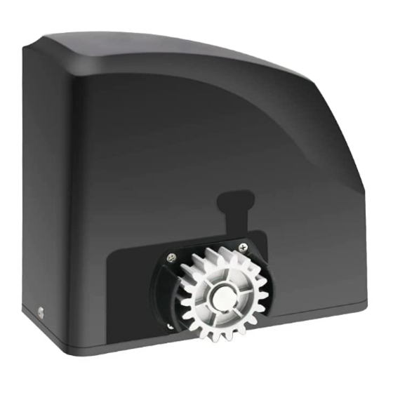
Sliding Gate Opener
User's Manual
Model:
DKR500(S/Y/T)
TOPENS Website
www.topens.com
Email: support@topens.com
★ Please read and follow all warnings, precautions and instructions before
installation and use.
★ Never connect the solar panel to the control board directly to charge the battery.
★ Periodic checks of the opener are required to ensure safe operation.
★ Save this manual.
C030566
VER 21b
Advertisement
Table of Contents

Related Manuals for Topens DKR500


Summary of Contents for Topens DKR500
- Page 1 Sliding Gate Opener User’s Manual Model: DKR500(S/Y/T) TOPENS Website www.topens.com Email: support@topens.com ★ Please read and follow all warnings, precautions and instructions before installation and use. ★ Never connect the solar panel to the control board directly to charge the battery.
- Page 2 Visit: www.topens.com Please record the product model, your email address etc. in the spaces provided below. Refer to this list when contacting TOPENS for technical service or assistance with your automatic gate opener. Where did you purchase? (Amazon.com; Amazon.ca: Amazon.co.uk, Amazon.de; Other, Please...
-
Page 3: Table Of Contents
Parts List ................................4 Extra Parts ................................ 4 Accessories Parts (Included in some models, refers to the actual package) ..........4 Optional Accessories Parts List (Available at TOPENS Store) ................ 4 Replacement Parts ............................5 Technical Specifications & Features ........................ 5 Installation Overview ............................ -
Page 4: Check Your Gate Before Installation
Thank you for purchasing our sliding gate opener. We are sure that the products will be greatly satisfying as soon as you start to use it. The product is supplied with a user’s manual which encloses installation and safety precautions. These should be read carefully before installation and operation as they provide important information about safety, installation, operation and maintenance. -
Page 5: Preparation For Installation
danger caused by squashing, conveying and shearing. • Position at least one visible indication device, and fix a Warning sign to the structure. • The factory declines all responsibility with respect to the automation safety and correct operation when other supplier’s components are used. •... - Page 6 In sake of safety, a positive stop must be mounted on the two end of ground track.
-
Page 7: Parts List
Parts List Extra Parts Accessories Parts (Included in some models, refers to the actual package) Optional Accessories Parts List (Available at TOPENS Store) M12 Remote Control ERM12 External TC186-R WiFi TC186 WiFi Smartphone Receiver Smartphone Remote Remote Control with Control with Camera... -
Page 8: Replacement Parts
RNH4 Heavy Duty Gear Rack Replacement Parts DKPYMJ1B Control PYMJ-CKG Limit Board Switch WARNING: Changes or modifications not expressly specified by this user manual, TOPENS could void the warranty of this equipment. Technical Specifications & Features Specifications Model: DKR500(S/Y/T) Power input:... -
Page 9: Installation Overview
·Built in adjustable auto-close (none, 30, 60, 90 Features: seconds) Soft start and soft stop ·Built in max. Motor Running Time (MRT) for multiple ·Midway mode safety protection (90 seconds) ·Quick selection for the gate open/close direction ·Reliable electromagnetism limit for easy adjustment ·Reliable rolling code technology for remote control ·Can be equipped with a wide range accessories ·Emergency release key in case of power failure... -
Page 10: Manual Operation
order to maintain proper stability. The installation proceeds are as follows: 1. Dig a hole for a concrete pad which should be approximately 40 x 24 x 30cm (15.7”x 9.4”x 11.8”). It may protrude 10 cm (4”) above ground and 20 cm (7.9”) in depth underground. Increase the pad height if necessary to protect the system from flooding, heavy snow etc. -
Page 11: Installation Of The Magnets
Installation of the Magnets Before install limit switch, make sure the gate opener is put in manual operation. (the clutch connected with gear shaft is disengaged) and the mains power supply is disconnected. Position the S&N Magnet Components approximately on the gate and move the gate by hand to fix them in place. - Page 12 been done. NOTE: 1. If batteries are chosen as the power source, Marine or Automotive Type Battery is required. The batteries should be waterproof type, or be placed in water proof circumstance. 2. 2 PCS 12VDC batteries can be connected in series to function as 24VDC. The following diagram shows on how to connect 2 PCS batteries in series.
- Page 13 Power Mode 4. By AC electricity and back-up batteries, use the AC electricity and the solar panel to charge the batteries at the same time If the AC electricity failure happens frequently and lasts for a long time (maybe 4-5 days one time), then you can charge the batteries with the AC electricity and the solar panel at the same time.
-
Page 14: Connecting Of The Control Board
Connecting of the Control Board 1. Motor The YELLOW wire of the motor should be connected into the “1” terminal. The RED wire of the motor should be connected into the “2” terminal. 2. Limit Switches The YELLOW wire of the limit switches should be connected into the “3” terminal. The BLACK wire of the limit switches should be connected into the “4”... - Page 15 The RED wire of the limit switches should be connected into the “5” terminal. 3. Warning Light (Included in some models, refers to the actual package) The WHITE wire of the warning light should be connected into the “6” terminal. The RED wire of the warning light should be connected into the “7”...
-
Page 16: Setting Of The Control Board
Setting of the Control Board WARNING: Ensure the gate opener is Power Off when you make any adjustment of the gate opener. Keep away from the path of the gate during you set the gate opener system in case of the unexpected gate moving. -
Page 17: Test The Reversing Sensitivity
DIP Switch #6–#7: Auto close time of the gate opener DIP Switch #6: ON – 30 Seconds OFF – 0 DIP Switch #7: ON – 60 Seconds OFF – 0 NOTE: The auto close function would be disabled if both DIP switches are turned to off (factory default setting). -
Page 18: How To Program Or Erase The Remote
All of TOPENS sliding gate opener have midway mode. Button B is designed to realize midway function (refer to more details in our TOPENS sliding gate opener manual). So it is must program button A with sliding gate opener, while you may program either C button or D button with TOPENS swing gate opener. -
Page 19: Troubleshooting
the default password “888888” to operate the opener after programming. You can press “PIN” “8 8 8 8 8 8” and then press “OK” to confirm to operate the opener. Also you can change the password of the keypad follow the below steps. Press “PIN” and then input the six digits old password and then press ”PIN”... -
Page 20: Maintenance
2. Check the motor. Release the clutch then disconnect the wires of the motor from terminal 1 and 2. Connect the wires to 24V battery directly, the motor should run, and then exchange the wires, the motor should run in the opposite direction. - Page 21 * Check for loose or corroded wire * Ensure the opener is well earthed, and correctly terminated. * Always check the Stop/Reverse in case of obstruction function when performing any maintenance. If this function can’t be made operable, remove this opener from service until the cause of the malfunction is identified and corrected.
- Page 22 Your comments and suggestions are important to us as they help us provide the best possible service. Should you have any need to contact us, the info below will help you get in touch: TOPENS Website www.topens.com Contact Us: E-mail: support@topens.com Kindly include your Product Model, Purchasing Date &...
Need help?
Do you have a question about the DKR500 and is the answer not in the manual?
Questions and answers