Table of Contents
Advertisement
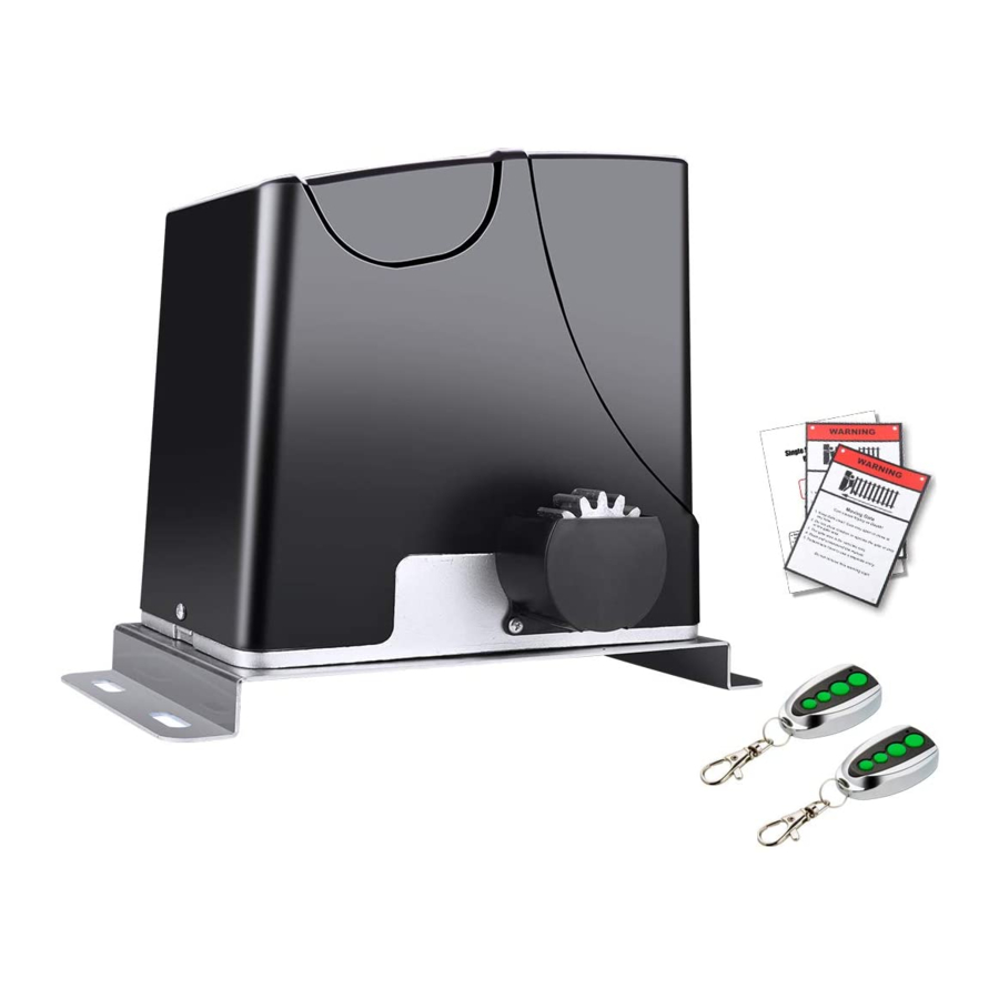
Sliding Gate Opener
User's Manual
Model:
DK1000(S/Y/T)
TOPENS Website
http://www.topenstool.com/
★ Please read and follow all warnings, precautions and instructions before
installation and use.
★ Never connect the solar panel to the control board directly to charge the battery.
★ Periodic checks of the opener are required to ensure safe operation.
★ Save this manual.
C030411
VER 20a
Advertisement
Table of Contents

Related Manuals for Topens DK1000


Summary of Contents for Topens DK1000
- Page 1 Sliding Gate Opener User’s Manual Model: DK1000(S/Y/T) TOPENS Website http://www.topenstool.com/ ★ Please read and follow all warnings, precautions and instructions before installation and use. ★ Never connect the solar panel to the control board directly to charge the battery. ★ Periodic checks of the opener are required to ensure safe operation.
-
Page 2: Table Of Contents
Parts List ………………………………………..….…………………………………..…………………………. 4 Extra Parts…………….…………………………………………………………………………………………..4 Accessories Parts (Included in some models, refers to the actual package) ….………………..………..… 5 Optional Accessories Parts List (Available at TOPENS Store) ….……….......………………..… 5 Technical Specifications & Features …………………….………………..…………………………………..5 Installation Overview ……………………………….…………..…………………………………..……………. 6 Installation of the Opener ……………………………………..…………………………………....……….6 Manual Operation …………………………………………..…………………………………..……………….. -
Page 3: General Safety
Thank you for purchasing our sliding gate opener. We are sure that the products will be greatly satisfying as soon as you start to use it. The product is supplied with a user’s manual which encloses installation and safety precautions. These should be read carefully before installation and operation as they provide important information about safety, installation, operation and maintenance. -
Page 4: Preparation For Installation
• Do not allow persons or children to remain in the automation operation area. • Keep radio control or other control devices out of children’s reach, in order to avoid unintentional automation activation. • The user must avoid any attempt to carry out work or repair on the automation system, and always request the assistance of qualified personnel. -
Page 5: Parts List
Parts List Extra Parts Rev 20a... -
Page 6: Accessories Parts (Included In Some Models, Refers To The Actual Package)
Accessories Parts (Included in some models, refers to the actual package) Optional Accessories Parts List (Available at TOPENS Store) Technical Specifications & Features Specifications Model: DK1000(S/Y/T) Power supply: 110V~120V/60Hz or 220~240V/50Hz Motor voltage: 24VDC Absorbed power: 350W Gate moving speed:... -
Page 7: Installation Overview
Features: ·Soft start and soft stop ·Midway mode. ·Quick selection for the gate open/close direction ·Reliable rolling code technology for remote control ·Emergency release key in case of power failure ·Stop in case of obstruction during gate opening ·Reverse in case of obstruction during gate closing ·Built in adjustable auto-close (none, 30, 60, 90 seconds) ·Built in max. -
Page 8: Manual Operation
* Before starting installation, ensure that there is no point of friction during the entire movement of the gate and there is no danger of derailment. * Ensure that the Warning Signs are present. Necessary Tools: The following tools may be necessary to install the Gate opener. You will need screwdrivers, an electric drill, wire cutters and a wire stripper, a socket set, and possibly access to a welder. -
Page 9: Fit The Rack
Fit the Rack There are two kinds of rack available as per your options, which are steel reinforced plastic rack and galvanized steel rack. The galvanized steel rack is usually used for the heavy duty gate. A. Fit the plastic rack reinforced with steel 1. -
Page 10: Installation Of The Magnets
3. Put one end of rack section on the gear of opener as a temporary support. Make rack level and mark the rack’s mounting holes (three holes) on the gate. 4. Weld the rack nut on the gate as mark and connect the rack to the gate using the bolt provided. Before weld, please keep 1.0mm space between the rack and the gear to avoid the weight of the gate effect on the opener. -
Page 11: Connecting Of The Batteries & Solar Panels & Solar Controller
1. Cut off the wire which has been connected between terminal 4 and 5 in factory to deactivate the existed short circuit of terminal 4 and 5. 2. Solder the two wires to the terminals of the switch respectively. NOTE: The power supply cord is not included in the package. NOTE: Make sure a residual current circuit breaker with a 30mA threshold is fitted before the power supply mains. -
Page 12: Connecting Of The Control Board
2. Using without AC electricity The gate opener also can be powered by 2 PCS 12VDC batteries (ONLY included in Y Series) as the main power supply with a 24VDC solar panel to charge it. The capacity of the batteries should be at least 12AH and the power of the solar panel should be at least 30W if there is totally no AC electricity. - Page 13 Use a 2-core cable to connect the “- ~” terminal of the photocell’s emitter to the “19” terminal, the “+ ~” terminal to the “18” terminal. Also the “- ~” and “+ ~” terminals of the photocell’s receiver should be connected to the “19”...
-
Page 14: Setting Of The Control Board
7. Battery (ONLY included in Y Series) The “24V+” of the battery should be wired to the BAT+ (11) terminal, “24V-” should be wired to “-BAT” (10) terminal. If the battery has been used with solar panel, please connect the batteries and the solar panel &solar controller refers to the chapter “Connecting of the Batteries &... - Page 15 DIP Switch #2: ON – 4 Seconds OFF – 0 NOTE: The midway mode function would be disabled if both DIP switches are turned off. Factory default setting is disabled. The midway mode could be activated by pressing button B of the remote control when the gate is in the full closed position.
-
Page 16: Test The Reversing Sensitivity
2. Potentiometers Potentiometer A is used to adjust the close stall force the gate operator. Turn clockwise to increase the stall force, and turn it counter-clockwise to decrease the stall force. Potentiometer B is used to adjust the open stall force the gate operator. Turn clockwise to increase the stall force, and turn it counter-clockwise to decrease the stall force. -
Page 17: How To Use The Remote To Operate Your Gate Opener
All of TOPENS sliding gate opener have midway mode. Button B is designed to realize midway function (refer to more details in our TOPENS sliding gate opener manual). So it is must program button A with sliding gate opener, while you may program either C button or D button with TOPENS swing gate opener. -
Page 18: Troubleshooting
Troubleshooting Have a multi-meter to check voltage and continuity. Use caution when checking high voltage terminals. Symptom Possible Solution(s) 1. Make sure that the power cord is properly plugged into the mains outlet. 2. Check if the output voltage of the transformer is 24VAC. If the voltage measures 0, the transformer may be overheated or damaged. -
Page 19: Maintenance
1. Please note the two limit magnets are different: one is N pole and another is S pole. Please try to exchange the two magnets. The gate opens, but 2. Please try to exchange the limit switch wires CL (close) and OP (open). stops and will not 3. - Page 20 TOPENS Website http://www.topenstool.com/ Any question, please do not hesitate to contact us: E-mail: support@topenstool.com Kindly include your Product Model, Purchasing Date & Site, Order #, and your contact information. All your concerns will be replied within 24 hours. Tel: +86 (571) 8908 0213 (China)
Need help?
Do you have a question about the DK1000 and is the answer not in the manual?
Questions and answers