Table of Contents
Advertisement
Fast Sliding Gate Opener
User's Manual
Model:
CF800
TOPENS Website
www.topens.com
Email: support@topens.com
★ Please read and follow all warnings, precautions and instructions before
installation and use.
★ Periodic checks of the opener are required to ensure safe operation.
★ Save this manual.
C030689
VER 23b
Advertisement
Table of Contents

Related Manuals for Topens CF800


Summary of Contents for Topens CF800
- Page 1 Fast Sliding Gate Opener User’s Manual Model: CF800 TOPENS Website www.topens.com Email: support@topens.com ★ Please read and follow all warnings, precautions and instructions before installation and use. ★ Periodic checks of the opener are required to ensure safe operation. ★ Save this manual.
- Page 2 Visit: www.topens.com Please record the product model, your email address etc. in the spaces provided below. Refer to this list when contacting TOPENS for technical service or assistance with your automatic gate opener. Where did you purchase? (Amazon.com; Amazon.ca: Amazon.co.uk, Amazon.de; Other, Please...
-
Page 3: Table Of Contents
Preparation for Installation........................... 2 Parts List ..............................4 Accessories Parts (Included in some models, refers to the actual package) ..........4 Optional Accessories Parts List (Available at TOPENS Store) ..............5 Replacement Parts ............................5 Technical Specifications & Features ......................6 Installation Overview ........................... -
Page 4: Check Your Gate Before Installation
Thank you for purchasing our sliding gate opener. We are sure that the products will be greatly satisfying as soon as you start to use it. The product is supplied with a user’s manual which encloses installation and safety precautions. These should be read carefully before installation and operation as they provide important information about safety, installation, operation and maintenance. -
Page 5: Preparation For Installation
• Position at least one visible indication device, and fix a Warning sign to the structure. • The factory declines all responsibility with respect to the automation safety and correct operation when other supplier’s components are used. • Only use original parts for any maintenance or repair operation. •... - Page 6 In sake of safety, a positive stop must be mounted on the two end of ground track.
-
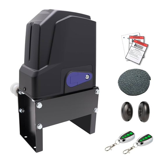
Page 7: Parts List
Parts List Accessories Parts (Included in some models, refers to the actual package) -
Page 8: Optional Accessories Parts List (Available At Topens Store)
Exit Wand Replacement Parts ACPYMJ7C Control ACPYMJ8C Control PYMJ-CKG Limit Switch Magnet Assembly(N Board (120V) Board (230V) pole & S pole) WARNING: Changes or modifications not expressly specified by this user manual, TOPENS could void the warranty of this equipment. -
Page 9: Technical Specifications & Features
Technical Specifications & Features Specifications CF800 Power input: 110~120V/60Hz or 220~240V/50Hz Motor voltage: 120VAC or 230VAC Rated power: 450W Gate moving speed: 40cm/s (16 in/s) for 120V 35cm/s (14 in/s) for 230V Max gate weight: 800kg (1800lbs) -20℃~ +50℃ (0°F to 120°F) -
Page 10: Installation Of The Opener
Installation of the Opener Caution: *Be sure that the opener is installed in a level and paralleled position. Improper installation could result in property damage, severe injury, and/or death. * Before starting installation, ensure that there is no point of friction during the entire movement of the gate and there is no danger of derailment. -
Page 11: Installation Of Chain And Chain Brackets
Installation of chain and chain brackets 1. Chain Brackets 1). Please refer to below chain brackets figure, which shows “U” bolt, “L” bracket and chain bolt. Use the “U” bolts (square or round) to attach the chain brackets to gate frame. 2). -
Page 12: Installation Of The Magnets
7). Make sure there is 1” distance at least between the wheel cover and the gate after you position the base plate. Installation of the Magnets Before install limit switch, make sure the gate opener is put in manual operation. (the clutch connected with gear shaft is disengaged) and the mains power supply is disconnected. -
Page 13: Connecting Of Power Supply
Connecting of Power Supply WARNING: NEVER connect the gate opener to the power outlet before all the installations have been done. The power supply cord should be at least 3×0.75mm (3C×18AWG). Connect the live wire and neutral wire to the “L” (1) and “N” (2) terminal of the control board respectively;... - Page 14 The RED wire of the motor should be connected into the “5” terminal. 2. Limit Switches The YELLOW wire of the limit switches should be connected into the “8” terminal. The BLACK wire of the limit switches should be connected into the “9” terminal. The RED wire of the limit switches should be connected into the “10”...
-
Page 15: Setting Of The Control Board
11. Exit Wand (optional) The BLACK wire of the exit wand should be connected into the “15” terminal. The BLUE wire of the exit wand should be connected into the “16” terminal. The RED wire of the exit wand should be connected into the“11” terminal. The GREEN wire of the exit wand should be connected into the“13”... -
Page 16: Test The Reversing Sensitivity
DIP Switch #4: Left/Right open 2. Potentiometers Potentiometer A and B are used to adjust the stall force and auto close time of the gate operator separately. Turn potentiometer A clockwise to increase the stall force, and turn it counter-clockwise to decrease the stall force. -
Page 17: How To Use The Remote To Operate Your Gate Opener
Each remote has four buttons, from top to bottom are separately A, B, C and D. You may use this remote to operate as many as 4 sets TOPENS swing gate openers or 1 set TOPENS sliding gate opener and 2 sets TOPENS swing gate openers. -
Page 18: Troubleshooting
digits old password and then press ”PIN” again, the LEARN LED will be ON. Input the six digits new password and then press the “PIN” to confirm the new setting, LEARN LED will flash for 3 seconds and then be OFF which indicates the password has been changed successfully. You can press “PIN” “6 digits new password”... -
Page 19: Maintenance
4. Check the control board. Replace the control board as necessary. 1. Check the wire connection of hall sensor board with the main control board. The gate starts but it 2. The opening force or closing force is adjusted too small. Turn the is immediately stop or Potentiometer A to increase the force. - Page 20 Your comments and suggestions are important to us as they help us provide the best possible service. Should you have any need to contact us, the info below will help you get in touch: TOPENS Website www.topens.com Contact Us: E-mail: support@topens.com Kindly include your Product Model, Purchasing Date &...
Need help?
Do you have a question about the CF800 and is the answer not in the manual?
Questions and answers