Table of Contents
Advertisement
Quick Links
★ Please read and follow all warnings, precautions and instructions before
installation and use.
★ Coming with UPS01 uninterrupted power supply, this series gate opener can be
powered by AC 100-240V electricity directly. It is allowed to use additional battery
(NOT incl.) and solar panel (optional) as BACK-UP or MAIN power source with this
UPS01.
★ Never connect the solar panel to the control board directly to charge the battery.
★ Periodic checks of the opener are required to ensure safe operation.
★ Save this manual.
C030569
Dual Swing Gate Opener
User's Manual
A3132 / A5132 / A8132
A3132S / A5132S / A8132S
TOPENS Website
www.topens.com
Email: support@topens.com
Model:
VER 21a
Advertisement
Table of Contents

Subscribe to Our Youtube Channel
Related Manuals for Topens A3132


Summary of Contents for Topens A3132
- Page 1 Dual Swing Gate Opener User’s Manual Model: A3132 / A5132 / A8132 A3132S / A5132S / A8132S TOPENS Website www.topens.com Email: support@topens.com ★ Please read and follow all warnings, precautions and instructions before installation and use. ★ Coming with UPS01 uninterrupted power supply, this series gate opener can be powered by AC 100-240V electricity directly.
- Page 2 Visit: www.topens.com Please record the product model, your email address etc. in the spaces provided below. Refer to this list when contacting TOPENS for technical service or assistance with your automatic gate opener. Where did you purchase? (Amazon.com; Amazon.ca: Amazon.co.uk, Amazon.de; Other, Please...
-
Page 3: Table Of Contents
A3132 Parts List ............................... 3 A5132/A8132 Parts List ........................... 4 Extra Parts for A3132 /5132 /8132 S ....................... 5 Accessories Parts (Included in some models, refers to the actual package) ..........5 Optional Accessories Parts List (Available at TOPENS Store) ................5 Replacement Parts ............................ -
Page 4: Safety Installation Information
use on any pedestrian gate. Pedestrians must be Safety Installation Information supplied with a separate pedestrian access. 1. READ and FOLLOW all instruction. For an installation utilizing non-contact sensors The gate opener is intended for use with Class I (safety sensors), see product manual on the vehicular swing gates. - Page 5 BEFORE digging. NOTE: TOPENS Gate Operator can be used for driveway gates made by steel, wood, vinyl, and shaped as panel, tube, and chain-link. While use on solid surface gates is NOT recommended. Solid surface gates have a...
-
Page 6: A3132 Parts List
A3132 Parts List... -
Page 7: A5132/A8132 Parts List
A5132/A8132 Parts List... -
Page 8: Extra Parts For A3132 /5132 /8132 S
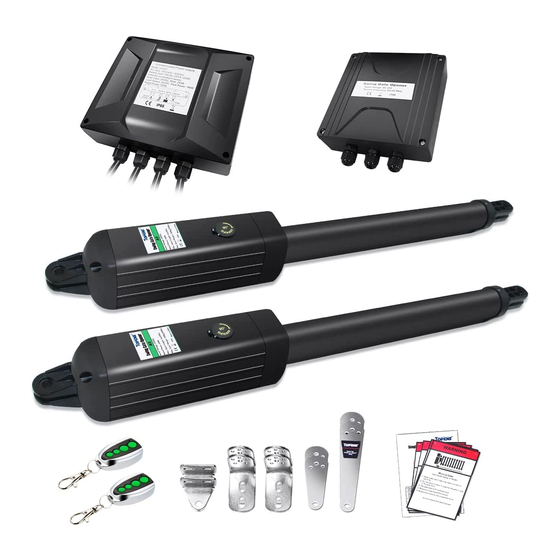
Extra Parts for A3132 /5132 /8132 S Accessories Parts (Included in some models, refers to the actual package) JD24VY 24V Warning TC102 Photo Eye Beam 25FT Extension Light Sensor 5 Conductor Cable Optional Accessories Parts List (Available at TOPENS Store) -
Page 9: Replacement Parts
Gate Opener Gate Opener UPS01 Uninterrupted MK01 Hardware Kit Power Supply WARNING: Changes or modifications not expressly specified by this user manual, TOPENS could void the warranty of this equipment. Tools Needed: ·Power Drill ·Tape Measure ·Open End Wrenches - 14# &17# or Adjustable Wrenches ·Wire Strippers... - Page 10 Current: 1.5A Actuator Speed: 16mm/s(0.6 in/s) Max. Actuator Travel: 385mm(15.2 in) Ambient Temperature: -20℃~ +50℃ (-4° F to 122° F) Protection Class: IP44 NOTE: “NR" indicates this size and weight combination recommended for one arm actuator. NOTE: Ball bearing hinges should be used on all gates weighing over 140kg (300 lbs).
-
Page 11: Installation Overview
Installation Overview Preparation for Installation There are two installation types for the gate opener, Pull-to-Open and Push-to-Open. In the Push-to-Open installation, gate opens out from the property. A Push-To-Open Bracket (PSO part) is required to be used for each gate. NOTE: Ensure the gate does not open into public areas. -
Page 12: Install The Opener On The Gate - For Pull To Open
Install the Opener on the Gate – for Pull to Open The position of Post Bracket is very important. The following illustrations and tables are required to determine the proper mounting position for the Post Bracket. The tables show the maximum opening angle of the gate for a given A and B. - Page 13 2. Attach the gate bracket and post bracket assy. to the opener by inserting a clevis pin. Secure the clevis pins using the hairpin clips. 3. Open the release hole plug on the top of the gate opener, insert the release key, and turn the key 90°...
- Page 14 5. Make sure that there is a minimum clearance of 2.5cm between the gate and the opener and that the opener and the Post Pivot Bracket are not binding in both the gate-open and gate-closed positions. If there is not at least 2.5cm of clearance or if the opener and the Post Pivot Bracket are binding, rotate the Post Pivot Bracket and/or move the Post Bracket Assy.
- Page 15 the opener and brackets assy. by taking off the C-clamps. 7. Drill 10.5 mm diameter holes through the post and the gate at the marked locations. 8. Attach the post bracket assemblies to the gate post by inserting M10 x 200 bolts through each post bracket assy.
-
Page 16: Install The Opener On The Gate - For Push To Open
12. Open the release hole plug on the top of the gate opener, insert the release key, and turn the key 90° counterclockwise. This restores normal operation. NOTE: The setting of the PULL/PUSH TO OPEN of the control board should be in accordance with the installation. - Page 17 1. Insert the bolts through the holes of post bracket and PSO part (push to open bracket) as shown. Place washers and nuts on the bottom of the bolts and hand tighten. 2. Attach the gate bracket and post bracket assy. to the opener by inserting a clevis pin. Secure the clevis pins using the hairpin clips.
- Page 18 5. Make sure that there is a minimum clearance of 2.5cm between the gate and the opener and that the opener and the PSO part are not binding in both the gate-open and gate-closed positions. If there is not at least 2.5cm of clearance or if the opener and the PSO part are binding, rotate the PSO part and/or move the Post Bracket Assy.
- Page 19 6. Sign the bolt-hole point on the gate post and gate. Do this by placing a punch or a sign in the middle of each bolt slot on the post bracket and the gate bracket. It allows slight adjustments to the post bracket.
- Page 20 10. Cut off any part of the bolts that extend beyond the tightened nuts. 11. With the opener fully retracted and with the gate in the fully closed position (for Push-to-Open installation), insert a clevis pin through the gate opener and the PSO part and insert another clevis pin through the gate opener and the Gate Bracket.
-
Page 21: Mounting Of The Control Box
12. Open the release hole plug on the top of the gate opener, insert the release key, and turn the key 90° counterclockwise. This restores normal operation. NOTE: The setting of the PULL/PUSH TO OPEN of the control board should be in accordance with the installation. -
Page 22: Connection Of The Power Supply
Connection of the Power Supply A 24VDC AC-DC power supply is included in the kit. You can plug it to the AC socket to use it power up the gate opener directly if the AC electricity is accessible. You can also connect a 24VDC back-up battery (2*12VDC, connected in series to become 24VDC) to the power supply if the AC electricity is not stable. - Page 23 Power Mode 2. By AC electricity and back-up batteries, only use the AC electricity to charge the batteries If the AC electricity failure happens rarely (less than 8 hours per day), then you can use minimum 5AH 2*12VDC batteries as back-up power source in case of AC power failure. In this situation, you can connect the UPS-01 to the control box refer to step 1 in this chapter.
- Page 24 wand and keypad). Please provide us with more details of the local sunshine condition and accessories needs which we can calculate the configuration of the solar panel and the batteries. Please connect the UPS-01 power supply & batteries & the solar panels refer to the following wiring diagram. You can leave the power cord Not Plugged in this situation.
-
Page 25: Connection Of The Control Board
Connection of the Control Board 1. Actuator 1 (Master gate, open first & close last) Insert the stripped cable wires into the appropriate terminals on the opener terminals block. The red wire should be inserted into the ―+MOTOR1‖ terminal(#15), the black wire into ―MOTOR1-‖ terminal (#16), the blue wire into ―ULMT1‖... - Page 26 Before connecting this item, please refer to the chapter of ―Connection of the Power Supply‖. 4. Battery not included) & solar panel (optional, ONLY included in A3132/A5132/A8132 S) Please connect them following the chapter of ―Connection of the Power Supply‖.
-
Page 27: How To Program The Remote To The Opener
250pcs remotes to be programmed for the opener. TOPENS ERM12 Universal External Receiver is available at TOPENS Store. TOPENS ERM12 Universal External Receiver is also compatible with other brand swing gate opener, sliding gate opener and garage door opener. -
Page 28: Wireless Keypad Programming
All of TOPENS sliding gate opener have midway mode. Button B is designed to realize midway function (refer to more details in our TOPENS sliding gate opener manual). So it is must program button A with sliding gate opener, while you may program either C button or D button with TOPENS swing gate opener. -
Page 29: Setting Of The Control Board
Note: The position of Limit Switch A was fixed in factory, do not adjust it again. 1 For Pull-to-Open Installation, adjust the limit switch B to determine the closed position: Turn on power to operate the gate opener, then the arm extends to close the gate. If the arm closes over the desired closed position, press the remote control to stop the opener. - Page 30 DIP Switch #1: Select push/pull to open If the gate opens into the property (pull to open), the DIP Switch is set to OFF (factory default setting). If your gate opens out from the property (push to open) the DIP Switch must be set to the ON position. Factory default setting is OFF.
-
Page 31: Maintenance
Potentiometer A is used to adjust the soft stop period of the gate opener. Turn the potentiometer clockwise to increase the soft stop period, and turn it counter-clockwise to decrease the soft stop period. The soft stop period can be adjusted gradually from 1 to 5 seconds. Potentiometer B is used to adjust the auto close time of the gate opener. -
Page 32: Status Of Led(S) & Trouble Shooting
Status of LED(s) & Trouble Shooting Status of LED(s) Status of gate Possible Solution(s) opener CODE LED POWER LED FULL LED Make sure connection between UPS01 and control box is correct and fastening. 2. Make sure the UPS01 power supply has been plugged into the AC main socket or the batteries (2*12V batteries connected... - Page 33 necessary. Flash(1 Blink every Normal (Output Voltage of Standby second) the UPS01 is normal) Flash(1 Blink every Flash(1 Blink every Flash(1 Blink Running Normal second ) second) every second) 1. Make sure the remote has been programmed to the control board before using.
- Page 34 second) 1. Two sequential contact Flash quickly for 10 entrapments have been Flash quickly for The gate stop when seconds and then detected. Please ensure 10 seconds and back flash there is no obstacle on the then back opening or closing slowly(1 Blink every path of opening or closing.
- Page 35 Your comments and suggestions are important to us as they help us provide the best possible service. Should you have any need to contact us, the info below will help you get in touch: TOPENS Website www.topens.com Contact Us: E-mail: support@topens.com Kindly include your Product Model, Purchasing Date &...
Need help?
Do you have a question about the A3132 and is the answer not in the manual?
Questions and answers