Table of Contents
Advertisement
Advertisement
Table of Contents

Related Manuals for Topens CK1200


Summary of Contents for Topens CK1200
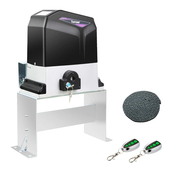
- Page 1 Sliding Gate Opener User’s Manual Model: CK1200 TOPENS Website http://www.topenstool.com/ ★ Please read and follow all warnings, precautions and instructions before installation and use. ★ Periodic checks of the opener are required to ensure safe operation. ★ Save this manual.
-
Page 2: Table Of Contents
Preparation for Installation ..........................2 Parts List ................................3 Accessories Parts (Included in some models, refers to the actual package) ..........4 Optional Accessories Parts List (Available at TOPENS Store) ................ 4 Technical Specifications & Features ........................ 4 Installation Overview ............................5 Installation of the Opener .......................... -
Page 3: General Safety
Thank you for purchasing our sliding gate opener. We are sure that the products will be greatly satisfying as soon as you start to use it. The product is supplied with a user’s manual which encloses installation and safety precautions. These should be read carefully before installation and operation as they provide important information about safety, installation, operation and maintenance. -
Page 4: Preparation For Installation
• Do not allow persons or children to remain in the automation operation area. • Keep radio control or other control devices out of children’s reach, in order to avoid unintentional automation activation. • The user must avoid any attempt to carry out work or repair on the automation system, and always request the assistance of qualified personnel. -
Page 5: Parts List
Parts List... -
Page 6: Accessories Parts (Included In Some Models, Refers To The Actual Package)
Accessories Parts (Included in some models, refers to the actual package) Optional Accessories Parts List (Available at TOPENS Store) Technical Specifications & Features Specifications CK1200 Power input: 110V~120V/60Hz or 220~240V/50Hz Motor voltage: 120VAC or 230VAC Rated power: 550W Gate moving speed:... -
Page 7: Installation Overview
Protection class: IP44 ·Emergency release key in case of power failure Features: Rev 20a ·Stop in case of obstruction during gate opening. ·Easy install, minimum maintenance Reverse in case of obstruction during gate closing requirement ·Built in adjustable auto-close (0, 30, 60, 90 seconds) ·Midway mode,Quick selection for gate open/close ·Built in max. - Page 8 2). Make sure there is 1” distance at least between the wheel cover and the gate after you position the base plate. Caution: *Be sure that the opener is installed in a level and paralleled position. Improper installation could result in property damage, severe injury, and/or death.
-
Page 9: Manual Operation
Manual Operation The opener should be put in the manual (emergency release) position before fitting the chain, installing the opener and limit switch. The process is as follows: 1) Insert and turn the key clockwise 45° to slide the lock cover. Now the key slot appears. 2) Insert the T-handle Key(provided)to the key slot and turn it in counter-clockwise 135°... -
Page 10: Installation Of The Magnets
Installation of the Magnets Before install limit switch, make sure the gate opener is put in manual operation. (the clutch connected with gear shaft is disengaged) and the mains power supply is disconnected. Position the two Magnet Components approximately on the gate and move the gate by hand to fix them in place. -
Page 11: Connecting Of Power Supply
Connecting of Power Supply WARNING: NEVER connect the gate opener to the power outlet before all the installations have been done. The power supply cord should be at least 3×0.75mm (3C×18AWG). Connect the live wire and neutral wire to the “L” (1#) and “N” (3#) terminal of the control board respectively;... - Page 12 The BLACK wire of the external receiver should be connected into the “13” terminal. The RED wire of the external receiver should be connected into the “12” terminal. 9. Wired Keypad (12VDC) (Optional) The RED wire of the wired keypad should be connected into the “12” terminal.
-
Page 13: Setting Of The Control Board
The BLACK wire of the wired keypad should be connected into the “13” terminal. The PURPLE wire of the wired keypad should be connected into the “16” terminal. The BLUE wire of the wired keypad should be connected into the “15” terminal. Setting of the Control Board WARNING: Ensure the gate opener is Power Off when you make any adjustment of the gate opener. -
Page 14: How To Program Or Erase The Remote
DIP Switch #5: Left/Right open ON – Left open (factory default setting). OFF – Right open. Turn switch OFF to change the opening direction easy if necessary. 2. Potentiometers The potentiometer A is to adjust the OPEN stall force of the gate opener. The Potentiometer B is used to adjust the CLOSE stall force of the gate opener. -
Page 15: How To Use The Remote To Operate Your Gate Opener
All of TOPENS sliding gate opener have midway mode. Button B is designed to realize midway function (refer to more details in our TOPENS sliding gate opener manual). So it is must program button A with sliding gate opener, while you may program either C button or D button with TOPENS swing gate opener. -
Page 16: Troubleshooting
NOTE: Every step for pressing button during program must be finished within 1 second to ensure successful programming. Troubleshooting Have a multimeter to check voltage and continuity. Use caution when checking high voltage terminals. Symptom Possible Solution(s) 1. Check the input voltage of the control board. It should be local AC electricity. -
Page 17: Maintenance
reverse 2. Disconnect the gate from the gate opener and check that the gate slides freely without any binding. 3. Check the control board. Replace the control board as necessary. 1. Check the installing position of the magnets. The opener would not run if both of the limit switches are activated by one magnet. - Page 18 TOPENS Website http://www.topenstool.com/ Any question, please do not hesitate to contact us: E-mail: support@topenstool.com Kindly include your Product Model, Purchasing Date & Site, Order #, and your contact information. All your concerns will be replied within 24 hours. Tel: +86 (571) 8908 0213 (China)
Need help?
Do you have a question about the CK1200 and is the answer not in the manual?
Questions and answers