Table of Contents
Advertisement
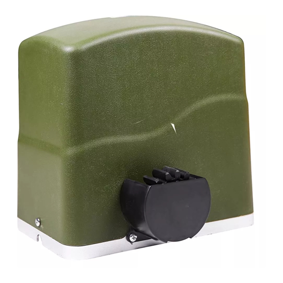
Sliding Gate Opener
User's Manual
Model:
RK700(T)
TOPENS Website
www.topens.com
Email: support@topens.com
★ Please read and follow all warnings, precautions and instructions before
installation and use.
★ Periodic checks of the opener are required to ensure safe operation.
★ Save this manual.
C030418
VER 21b
Advertisement
Table of Contents

Related Manuals for Topens RK700


Summary of Contents for Topens RK700
- Page 1 Sliding Gate Opener User’s Manual Model: RK700(T) TOPENS Website www.topens.com Email: support@topens.com ★ Please read and follow all warnings, precautions and instructions before installation and use. ★ Periodic checks of the opener are required to ensure safe operation. ★ Save this manual.
- Page 2 Visit: www.topens.com Please record the product model, your email address etc. in the spaces provided below. Refer to this list when contacting TOPENS for technical service or assistance with your automatic gate opener. Where did you purchase? (Amazon.com; Amazon.ca: Amazon.co.uk, Amazon.de; Other, Please...
-
Page 3: Table Of Contents
Parts List ................................4 Extra Parts for RK700T ............................ 4 Accessories Parts (Included in some models, refers to the actual package) ..........4 Optional Accessories Parts List (Available at TOPENS Store) ................ 4 Replacement Parts ............................5 Technical Specifications & Features ........................ 5 Installation Overview ............................ -
Page 4: Check Your Gate Before Installation
Thank you for purchasing our sliding gate opener. We are sure that the products will be greatly satisfying as soon as you start to use it. The product is supplied with a user’s manual which encloses installation and safety precautions. These should be read carefully before installation and operation as they provide important information about safety, installation, operation and maintenance. -
Page 5: Preparation For Installation
• Position at least one visible indication device, and fix a Warning sign to the structure. • The factory declines all responsibility with respect to the automation safety and correct operation when other supplier’s components are used. • Only use original parts for any maintenance or repair operation. •... - Page 6 In sake of safety, a positive stop must be mounted on the two end of ground track.
-
Page 7: Parts List
Parts List Extra Parts for RK700T Accessories Parts (Included in some models, refers to the actual package) Optional Accessories Parts List (Available at TOPENS Store) M12 Remote Control ERM12 External TC186-R WiFi TC186 WiFi Receiver Smartphone Remote Smartphone Remote Control with Camera... -
Page 8: Replacement Parts
Replacement Parts ACPYMJ5A Control ACPYMJ6A Control PYMJ-CKG Limit Switch Board (120V) Board (230V) WARNING: Changes or modifications not expressly specified by this user manual, TOPENS could void the warranty of this equipment. Technical Specifications & Features Specifications RK700(T) Power supply:... -
Page 9: Installation Overview
·Stop in case of obstruction during gate opening ·Reverse in case of obstruction during gate closing ·Built in adjustable auto-close (1-99 seconds) ·Built in max. Motor Running Time (MRT) for multiple safety protection (90 seconds) ·Reliable electromagnetism limit for easy adjustment ·Can be equipped with a wide range accessories ·Easy to install, and minimum maintenance requirement Installation Overview... -
Page 10: Manual Operation
have to pass through the hole in opener base. 3. Pour concrete and before it starts to harden, check that it is parallel to the gate leaf and perfectly level. 4. The four anchor bolts must be set into the concrete when it is poured, make sure the position of anchor bolts was placed according to the position of mounting holes on the opener... -
Page 11: Installation Of The Magnets
Installation of the Magnets Before install limit switch, make sure the gate opener is put in manual operation. (the clutch connected with gear shaft is disengaged) and the mains power supply is disconnected. Position the S&N Magnet Components approximately on the gate and move the gate by hand to fix them in place. -
Page 12: Connecting Of Power Supply
Connecting of Power Supply WARNING: NEVER connect the gate opener to the power outlet before all the installations have been done. The power supply cord should be at least 3×0.75mm (3C×18AWG). Connect the live wire and neutral wire to the “L” (2) and “N” (1) terminal respectively; and connect the earth wire to “PE”. -
Page 13: Setting Of The Control Board
2. Limit Switches The YELLOW wire of the limit switches should be connected into the “8” terminal. The BLACK wire of the limit switches should be connected into the “9” terminal. The RED wire of the limit switches should be connected into the “10” terminal. 3. - Page 14 the gate operator installed. DIP Switch #1–#2: Running time of the motor in Midway Mode DIP Switch #1: ON – 2 Seconds OFF – 0 DIP Switch #2: ON – 4 Seconds OFF – 0 NOTE: The midway mode function would be disabled if both DIP switches are turned off.
-
Page 15: Test The Reversing Sensitivity
Test the Reversing Sensitivity For the sake of safety, it is very important to test the reversing sensitivity as soon as the control board set is finished. The reversing sensitivity adjustment is inverse correlation with stall force adjustment in potentiometer A. In other word, the stall force level is higher;... -
Page 16: How To Use The Remote To Operate Your Gate Opener
All of TOPENS sliding gate opener have midway mode. Button B is designed to realize midway function (refer to more details in our TOPENS sliding gate opener manual). So it is must program button A with sliding gate opener, while you may program either C button or D button with TOPENS swing gate opener. -
Page 17: Troubleshooting
Troubleshooting Have a multimeter to check voltage and continuity. Use caution when checking high voltage terminals. Symptom Possible Solution(s) 1. Check the input voltage of the control board. It should be local AC electricity. 2. Check the fuse in the control board. Replace the fuse if it was burnt out. 3. -
Page 18: Maintenance
1. Photocell is obstructed. Remove obstruction. 2. Check the limit switch. Remove the wire connection of the limit switch which The gate can open, is connected to the 8#, 9#, and 10# terminals of the control board and then but fails to close. use a jumper wire to short the 3 terminals together to try it again. - Page 21 Your comments and suggestions are important to us as they help us provide the best possible service. Should you have any need to contact us, the info below will help you get in touch: TOPENS Website www.topens.com Contact Us: E-mail: support@topens.com Kindly include your Product Model, Purchasing Date &...
Need help?
Do you have a question about the RK700 and is the answer not in the manual?
Questions and answers