Table of Contents
Advertisement
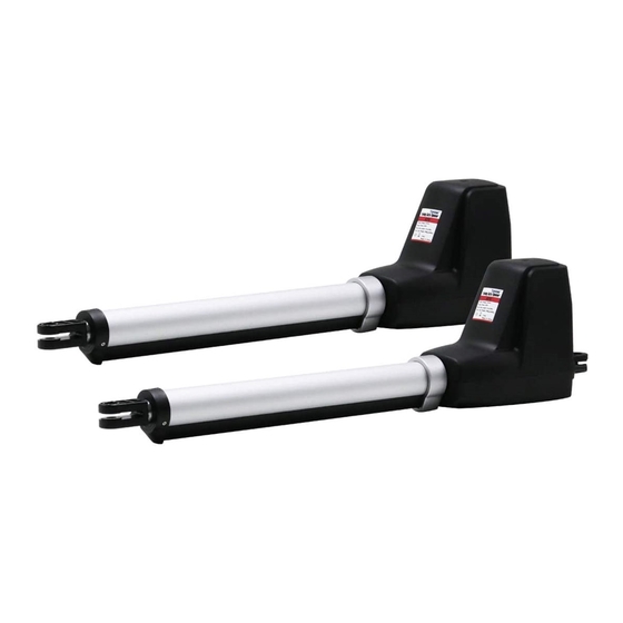
Dual Swing Gate Opener
User's Manual
Model:
AT602
TOPENS Website
http://www.topenstool.com/
★ Please read and follow all warnings, precautions and instructions before
installation and use.
★ Never connect the solar panel to the control board directly to charge the battery.
★ Periodic checks of the opener are required to ensure safe operation.
★ Save this manual.
C030472
VER 20a
Advertisement
Table of Contents

Related Manuals for Topens AT602


Summary of Contents for Topens AT602
- Page 1 Dual Swing Gate Opener User’s Manual Model: AT602 TOPENS Website http://www.topenstool.com/ ★ Please read and follow all warnings, precautions and instructions before installation and use. ★ Never connect the solar panel to the control board directly to charge the battery.
-
Page 2: Table Of Contents
Safety Installation Information ........................1 AT602 Parts List ............................2 Accessories Parts (Included in some models, refers to the actual package) ............3 Optional Accessories Parts List (Available at TOPENS Store) ................3 Tools Needed: ............................... 3 Technical Specifications & Features ......................4 Installation Overview ............................. -
Page 3: Safety Installation Information
use on any pedestrian gate. Pedestrians must be Safety Installation Information supplied with a separate pedestrian access. 1. READ and FOLLOW all instruction. For an installation utilizing non-contact sensors The gate opener is intended for use with Class I (safety sensors), see product manual on the vehicular swing gates. -
Page 4: At602 Parts List
13. To AVOID damaging gas, power, or other SAVE INSTRUCTION. underground utility lines, contact underground utility 14. Do not permit children to play on or around the locating companies BEFORE digging. gate and keep all controls out of their reach. AT602 Parts List... -
Page 5: Accessories Parts (Included In Some Models, Refers To The Actual Package)
Accessories Parts (Included in some models, refers to the actual package) Optional Accessories Parts List (Available at TOPENS Store) Tools Needed: ·Power Drill ·Tape Measure ·Open End Wrenches — 14# &17# or Adjustable Wrenches ·Wire Strippers ·C-Clamps — small, medium, and large ·Level... -
Page 6: Technical Specifications & Features
Technical Specifications & Features Specifications Model: AT602 Input: 110V~120V/60Hz or 220~240V/50Hz Motor voltage: 24VDC 2×50W Power: Current: Actuator speed: 16mm/s(0.6 in/s) Max. actuator travel: 385mm(15.2 in) -20℃~ +50℃ (-4°F to 122°F) Ambient Temperature: Protection class: IP44 Features: adjustable for multiple safety protection (1-50 ·Soft start and soft stop... -
Page 7: Installation Overview
Installation Overview Pull-to-Open Gates Important: The second gate opener cable should be put into the PVC conduit (not provided) which is buried underground .This protects the cable from lawn mowers and string trimmers. Rev 20a... -
Page 8: Preparation For Installation
Preparation for Installation There are two installation types for the gate opener, Pull-to-Open and Push-to-Open. In the Push-to-Open installation, gate opens out from the property. A Push-To-Open Bracket (PSO part) is required to be used for each gate. NOTE: Ensure the gate does not open into public areas. The gate opener is mounted to the gate and to the gate post. - Page 9 Push-to-Open Installation — Gate in Closed position (Moving-Rod is retracted) 1. Insert the M10 x 30 bolt through the center hole of the post bracket and post pivot bracket as shown. Place a ¢10 washer , ¢10 lock washer and M10 nut on the bottom of the bolt and hand tighten. 2.
- Page 10 5. Make sure that there is a minimum clearance of 2.5cm between the gate and the opener and that the opener and the Post Pivot Bracket are not binding in both the gate-open and gate-closed positions. If there is not at least 2.5cm of clearance or if the opener and the Post Pivot Bracket are binding, rotate the Post Pivot Bracket and/or move the Post Bracket Assembly to obtain the minimum clearance and eliminate the binding.
- Page 11 6. Sign the bolt-hole point on the gate bracket and gate. Do this by placing a punch or a sign in the middle of each bolt slot on the post bracket assemblies and the gate bracket. It allows slight adjustments to the post bracket.
-
Page 12: Mounting The Control Box
12. Open the release hole plug on the top of the gate opener, insert the release key, and turn the key 90° counterclockwise. This restores normal operation. Mounting the Control Box Step 1 To install the control box use the deck screws (not provided). Even though the control box is waterproof designed, for safety reason and a longer service life, it is recommended to install the control box inside a secure surface and at least 100 cm (40 inches) above the... -
Page 13: Connection Of Power Supply
Step 3 Insert the cable of the motor2 and alarm lamp cables into the control box through middle strain relief. Then repeat step 2. Step 4 Insert other cables into the control box through rightmost strain relief. Then repeat step 2. CAUTION: Make sure the cable outlet hole in the Control Box is always down during installation so as to drain off the water. -
Page 15: How To Program Or Erase The Remote
Warning Light (Included in some models, refers to the actual package) The red wire of the warning light should be inserted into either +LAMP (#11) terminal, the white wire into the LAMP- (#12) terminal. Back-up Battery & Solar Panel & Solar Controller (optional) If there is no solar panel to be used for charging the battery, then the “24V+”... -
Page 16: How To Use The Remote To Operate Your Gate Opener
All of TOPENS sliding gate opener have midway mode. Button B is designed to realize midway function (refer to more details in our TOPENS sliding gate opener manual). So it is must program button A with sliding gate opener, while you may program either C button or D button with TOPENS swing gate opener. -
Page 17: Setting Of The Control Board
Setting of the Control Board WARNING: Ensure the gate opener is Power Off when you make any adjustment of the gate opener. Keep away from the path of the gate during you set the gate opener system in case of the unexpected gate moving. - Page 18 Press the “FUNC” button to store the data when the close interval is set. The Digital Display will indicate “P5”. Now Close Interval Set is finished. 6. Adjust the Obstruction Sensitivity/Stall Force When the Digital Display indicates “P5”, the gate opener is on the Stall Force Adjustment. Without a properly installed safety reversal system, person (particularly small children) could be SERIOUSLY INJURED or KILLED by a closing gate.
- Page 19 MOTOR2 adjustment is finished. 8. Set the Safety Photocell Beam System (PBS) (Optional) When the Digital Display indicates “P9”, the gate opener enters PBS set mode. You can press and release the “INC” or “DEC” button to set or shut off the PBS function. The Digital Display indicates “11”, the PBS is available.
-
Page 20: Indicate Illustration On The Digital Display When Gate Opener Is Running
Indicate Illustration on the Digital Display When Gate Opener is Running The left image on Digital Display symbolizes motor of gate opener 2 when the gate opener is running. The right image on Digital Display symbolizes motor of gate opener 1. When the motor is run to gate -open direction or gate -close direction, the image on Digital Display indicates “n”... -
Page 21: Maintenance
Maintenance Warning: Disconnect power before servicing. 1. Using a clean, dry cloth to wipe the gate opener shaft, and then apply a silicone spray to reduce its friction. In cold climates where temperatures reach 1°C (30°F) or less, spray silicone on the actuator every 4~6 weeks to prevent freeze up. - Page 22 ◆ Gate ignores the limit switches 1. Check that the wires of the limit switch (BLUE&GREEN&YELLOW wires of the arm) are not shorted. 2. Limit switch of the arm is faulty. Replace the limit switch as necessary. ◆Gate opens, closes or stops on its own 1.
-
Page 23: Quick-Setting Guide
Quick-Setting Guide... - Page 27 TOPENS Website http://www.topenstool.com/ Any question, please do not hesitate to contact us: E-mail: support@topenstool.com Kindly include your Product Model, Purchasing Date & Site, Order #, and your contact information. All your concerns will be replied within 24 hours. Tel: +86 (571) 8908 0213 (China)
Need help?
Do you have a question about the AT602 and is the answer not in the manual?
Questions and answers