Table of Contents
Advertisement
Quick Links
Advertisement
Table of Contents

Related Manuals for DSC neo 3G8080I


Summary of Contents for DSC neo 3G8080I
- Page 1 3G8080(I)/ CD8080(I) HSPA/CDMA Controller V1.1 Installation Manual WARNING: This manual contains information on limitations regarding product use and function and information on the limitations as to liability of the manufacturer. The entire manual should be carefully read.
-
Page 3: Table Of Contents
Table of Contents Warning: Installer Please Read Carefully Note to Installers System Failures Access by Intruders Component Failure Compromise of Radio Frequency (Wireless) Criminal Knowledge Failure of Replaceable Batteries Inadequate Installation Inadequate Testing Insufficient Time Motion Detectors Power Failure Security and Insurance Smoke Detectors Telephone Lines Warning Devices... - Page 4 Table of Contents Clock Troubleshooting Module Status Information Troubleshooting LEDs LED Functions LED Details LED L1 (Red) LED L2 (Yellow) LED L3 (Yellow) LED L4 (Green) LED L5 (Yellow) Various Module States (Modes) Improving Wireless Signal Strength Walking the Customer through New User Setup on the Web Interactive Service Menu Interactive Menus Installer Programming...
-
Page 5: Warning: Installer Please Read Carefully
Inadequate Installation Warning: Installer Please Read A security system must be installed properly in order to provide Carefully adequate protection. Every installation should be evaluated by a secur- ity professional to ensure that all access points and areas are covered. Locks and latches on windows and doors must be secure and operate Note to Installers as intended. -
Page 6: Security And Insurance
Security and Insurance Regardless of its capabilities, an alarm system is not a substitute for property or life insurance. An alarm system also is not a substitute for property owners, renters, or other occupants to act prudently to pre- vent or minimize the harmful effects of an emergency situation. Smoke Detectors Smoke detectors that are a part of this system may not properly alert occupants of a fire for a number of reasons, some of which follow. -
Page 7: General
This installation guide provides the basic wiring, programming and troubleshooting information. Use this guide in conjunction with the installation manual available online from the DSC website at www.dsc.com. The HSPA/CDMA alarm communicator is a fixed, wall-mounted unit, and shall be installed in the location spe- cified in these instructions. -
Page 8: Hspa/Cdma 3G Module - 3G8080(I)/Cd8080(I)
HS2016 software versions 1.1 and above. HSPA/CDMA 3G Module - 3G8080(I)/CD8080(I) The HSPA/CDMA module enables wireless reporting of all alarms and other system events from the DSC Neo control panel using an all-digital, HSPA/CDMA wireless (cellular) network. The module can be used as the primary communication path for all alarm signaling, or as a backup to a telephone connection to the central monitoring station. -
Page 9: Communicator Compatibility
Model 3G8080(I) CD8080(I) Humidity 90% non-condensing Mechanical Spec7ifications Dimensions 6" x 8.9" x 1.3" Weight (grams) 365g (I) 360g (I) Communicator Compatibility Receiver/ Communicator Description Panel Sur-Gard System I-IP Receiver, version 1.13+ Sur-Gard System II Receiver, version 2.10+ Sur-Gard SG-DRL3-IP, version 2.30+ (for Sur-Gard System III Receiver) 3G8080(I) Receiver... -
Page 10: Installation
Installation NSTALLATION Follow these guidelines during installation. Before affixing the communicator to a wall, verify the HSPA/CDMA signal level at the installation loc- ation. On a keypad, press and hold the 5 key for 2 seconds to view the HSPA/CDMA signal level. An installation location with a sustained signal level of two or more bars is recommended. -
Page 11: Enable Module
Installation Mounted in Alarm Controller Cabinet HSPA/CDMA Controller Board +12V +12V PCL-422 A Red wire on alarm controller PCLink_2 Header B Antenna access ports C Quad cables (100' / 30m maximum) D Red wire on PCL-422 PCLink Header E HSPA/CDMA Controller Board power terminals. Can be connected to power supply module (HSM2204/2300). Enable Module For the Alarm.com module to communicate with the panel, section [382] option 5 at the panel must be set to ON. -
Page 12: Step 3: Connect The Pc-Link Cable
Upgraded antennas are available for the 3G8080(I) /CD8080(I) if there is inadequate cellular reception at the preferred mounting location. Contact DSC technical support for antenna options. The 3G8080(I)/CD8080(I) has two covered access ports on the top of the enclosure. Remove the plastic tab covering the desired port and either mount the antenna on the enclosure or use the opening to pass through the antenna cable. -
Page 13: Panel Settings
Installation 6. Insert the batteries into the sensor. Wait approximately 20 seconds for the control panel screen to display: “I.S. [x] Added as Sensor [y].” The LED on the sensor will turn solid for 5 seconds once the sensor has enrolled. -
Page 14: Notifications
Installation Section Option Description 311 [002] Partition 1 Call Direction - Tamper/Restore 311 [003] Partition 1 Call Direction - Opening/Closing 312 [001] Partition 2 Call Direction - Alarm/Restore 312 [002] Partition 2 Call Direction - Tamper/Restore 312 [003] Partition 2 Call Direction - Opening/Closing 313 [001] Partition 3 Call Direction - Alarm/Restore 313 [002]... -
Page 15: Clock
Installation Section Option Value Description Daylights saving time must be disabled to ensure panel time is accurate Set according to Enables Duress Code changes from dealer's Alarm.com Alarm.com setting Realtime clock must be disabled to ensure panel time is accurate User Access Codes must be 4-digits Swinger Shutdown for maintenance signals Swinger Shutdown... -
Page 16: Troubleshooting
Troubleshooting ROUBLESHOOTING Module Status Information Module status information for verifying and troubleshooting the module connection status or errors can be found through the Interactive Services menus. To access these, press [*][8][Installer Code][851]. See the fol- lowing table for potential module states. Status Description Idle... -
Page 17: Led Functions
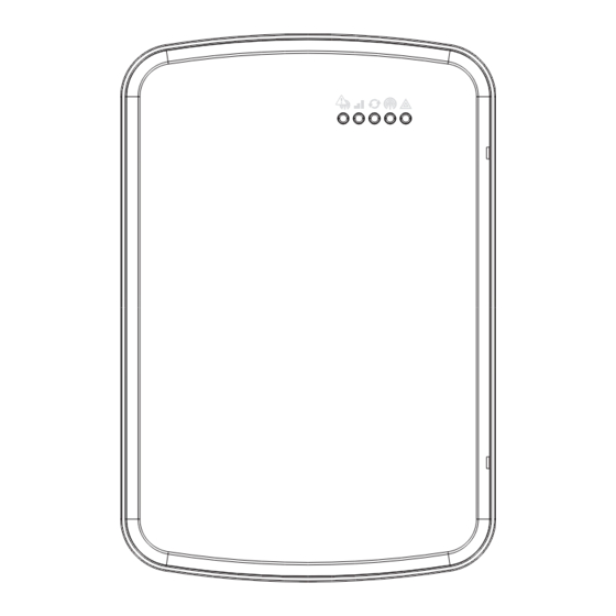
Troubleshooting Status LEDs L1 L2 L3 L4 L5 LED Functions Function Error LED. Flashes 1 to 8 times in an 8-second interval to indicate specific error. See section "LED L1 (red)" for errors and common fixes. Panel Communication and Z-Wave status messages. Flashes every time the module communicates with the panel and flashes in patterns to indicate Z-Wave status. -
Page 18: Led L2 (Yellow)
Troubleshooting Number Error and Solution Flashes The SIM card is missing. The SIM card holder can be found on the module. Verify that the SIM card holder is closed securely and that there is a SIM card in the holder. The module is trying to register on the HSPA/CDMA network. -
Page 19: Led L5 (Yellow)
Troubleshooting Signal level is updated every ten seconds if it fluctuates, or every 30 seconds if it is fairly stable. If L4 is not flashing it indicates one of the following states: The module is in PowerSave mode The module just powered up There is no HSPA/CDMA coverage in the area. -
Page 20: Improving Wireless Signal Strength
Install the module near or adjacent to an exterior-facing wall of the structure. Do not install the module inside a metal structure or close to large metal objects or ducts. Upgrade the antenna. Contact DSC technical support for antenna options. Walking the Customer through New User Setup on the Web This section describes how to help your customer set up their website account, and only applies to customers on an interactive service plan with an online account. -
Page 21: Interactive Service Menu
Interactive Service Menu NTERACTIVE ERVICE Interactive Menus The “Interactive Services” menu can be used to access information about the HSPA/CDMA module, install or remove Z-Wave devices and configure or troubleshoot other interactive features. To enter the menu, press [*] [8] [Installer Code] [851]. The menu will time out after 20 minutes. -
Page 22: User Functions
Interactive Service Menu Menu Description Signal strength of the communication between image sensor and image sensor -----Signal daughterboard -----Test PIR Press [*] to put the image sensor in PIR Test Mode Press [*] to view current selection. Scroll down to view sensitivity levels. Press [*] -----PIR Sensitivity to select -----Rules... -
Page 23: Limited Warranty
DSC's option. Products not covered by this warranty, or be free of defects in materials and workmanship under normal use. -
Page 24: End User License Agreement
Termination - Without prejudice to any other rights, DSC may ter- agree to the terms of this EULA, DSC is unwilling to license the minate this EULA if You fail to comply with the terms and conditions SOFTWARE PRODUCT to You, and You have no right to use it. -
Page 25: Limited Warranty
INCLUDING CUSTOMERS, AND INJURY TO PROPERTY. ARBITRATION - All disputes arising in connection DSC recommends that the entire system be completely tested on a reg- ular basis. However, despite frequent testing, and due to, but not lim- with this Agreement shall be determined by final and... -
Page 26: Fcc/Ic Label
L'exploitation est autorisée aux deux conditions suivantes : (1) l'ap- For ULC Residential Fire and Burglary installations the 3G8080 (I) pareil ne doit pas produire de brouillage, et (2) l'utilisateur de l'appareil /CD8080(I) is listed as a sole means communication or as a back up doit accepter tout brouillage radioélectrique subimême si le brouillage when used in conjunction with a POTS line (dialer). - Page 28 © 2015 Tyco Security Products. All Rights Reserved. Tech Support: 1-800-387-3630 (Canada & U.S.) or 905-760-3000 www.dsc.com The trademarks, logos, and service marks displayed on this document are registered in the United States [or other countries]. Any misuse of the trade- marks is strictly prohibited and Tyco will aggressively enforce its intellectual property rights to the fullest extent of the law, including pursuit of crim- inal prosecution wherever necessary.
Need help?
Do you have a question about the neo 3G8080I and is the answer not in the manual?
Questions and answers