Table of Contents
Advertisement
Quick Links
To download the full installation and user manuals and register your
product, please visit:
www.DSC.com/m/29009866 or scan the QR code to the right.
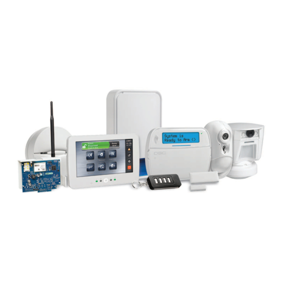
HS2016/HS2016-4/HS2032/HS2064/HS2064 E/
HS2128/HS128 E Alarm Panel
WARNING: This manual contains information on limitations regarding product use and function and
information on the limitations as to liability of the manufacturer. The entire manual should be care-
fully read.
User Guide (UK)
Advertisement
Table of Contents

Related Manuals for DSC neo HS128 E


Summary of Contents for DSC neo HS128 E
- Page 1 To download the full installation and user manuals and register your product, please visit: www.DSC.com/m/29009866 or scan the QR code to the right. HS2016/HS2016-4/HS2032/HS2064/HS2064 E/ HS2128/HS128 E Alarm Panel User Guide (UK) WARNING: This manual contains information on limitations regarding product use and function and information on the limitations as to liability of the manufacturer.
-
Page 2: Table Of Contents
Table of Contents 1.0 Quick Reference 2.0 Understanding Your Keypad 2.1 Icon and LED Keypad Symbols 2.2 Keypad Models 3.0 The PowerSeries Neo Security System 3.1 General System Operation 3.2 Testing Your System 3.3 Monitoring 4.0 Setting the Alarm System 4.1 Alarm System Setting Methods 4.2 Setting the System (Infinite Exit Delay) 4.3 Away Setting the System with the Keypad... -
Page 3: Quick Reference
For detailed information about the PowerSeries Neo Alarm System, refer to the full online manual, which can be accessed from the DSC.com Web site. Note: Some features must be enabled by installer. Note: Bypass Groups are not permitted in UL listed installations. - Page 4 Chapter 1.0 Quick Reference Action Press Bypass Individual Zones [3 Digit Zone #] Bypass All Open Zones [9][9][8] Recall Last Bypass [9][9][9] Clear Bypass [0][0][0] OR [Scroll] Bypass Options + [*] + [Scroll] Clear Bypasses + [*] Program Bypass Group [3 digit zone #s] + [9][9][5] OR [3 digit zone #s] + [Scroll] Bypass Options + [*] + [Scroll] Prg Bypass Group + [*]...
-
Page 5: Understanding Your Keypad
Chapter 2.0 Understanding Your Keypad 2.0 Understanding Your Keypad The PowerSeries Neo Alarm System supports a variety of wireless, hardwired and proximity sensor LCD, LED and Icon keypads. All keypads come equipped with the LED status lights described in section 1 "Quick Reference". HS2LCD series keypads display system messages on their LCD screen. -
Page 6: Keypad Models
Chapter 2.0 Understanding Your Keypad Chime This icon turns on when the Chime function key is pressed to enable Door Chime on the system. It will turn off when the chime function key is pressed again to disable Door Chime. OPEN This icon is used with clock digits 1 and 2 to indicate activated zones (not alarm) on the system. -
Page 7: The Powerseries Neo Security System
Chapter 3.0 The PowerSeries Neo Security System 3.0 The PowerSeries Neo Security System Your PowerSeries Neo has been designed to provide you with the greatest possible flexibility and convenience. Read this manual carefully and have your installer instruct you on how to operate your system and which features have been implemented in your system. -
Page 8: Setting The Alarm System
Chapter 4.0 Setting the Alarm System 4.0 Setting the Alarm System 4.1 Alarm System Setting Methods The PowerSeries Neo system is capable of completing the full alarm system setting procedure using one of the following methods: push button switch mounted outside the supervised premises; or protective switch (i.e., door contact) fitted to the final exit door of the alarmed premises or area. -
Page 9: Exit Delay Time Restart
Chapter 4.0 Setting the Alarm System After successfully initiating the setting sequence the: Exit Delay in Progress indicator turns on. Ready indicator remains lit. Exit Delay timer begins counting down. Keypad beeps six times, continues beeping once per second until beeping rapidly in the final ten seconds. The system may be configured to have a persistent exit delay that only ends when the exit door is opened and closed, or when a button is pressed outside the protected... -
Page 10: Setting The System With A 2-Way Wireless Key
Chapter 4.0 Setting the Alarm System Away Set Away Set Stay Set Stay Set Unset Unset Panic Panic Command Output 1 Command Output 1 Message LED Status LEDs Note: Panic feature has not been evaluated by UL. All wireless key buttons are programmable. Verify the functions assigned to each key with your installer. -
Page 11: Engineers Reset
During this time, the panel will answer incoming downloading calls. DLS-3 downloading software allows you to program and control supported DSC security systems from any PC-compatible com- puter. DLS-3 can send data and programming information to, and retrieve it from security systems using a modem, or using the DSC PC- LINK device. -
Page 12: Access Code Types
Chapter 5.0 Access Code Types 5.0 Access Code Types The alarm system provides the following user access code types: Code Add User Delete Set Unset Access User Func- Installer User Codes tions Master Yes Yes User Yes Yes All but All but Yes Yes Supervisor... -
Page 13: Adding, Changing And Deleting Access Codes
Chapter 5.0 Access Code Types To Open the Access Codes Menu LCD Display Press [*][5] Press (*) for <> Access Codes press [*] and use the scroll keys to navigate to Access Codes and press [*]. Enter [Master or supervisor code]. Present Tag or Enter Code Enter [User #]... -
Page 14: Burglary Verification
Chapter 5.0 Access Code Types 5.2 Burglary Verification The Control Panel includes sequential detection features that require a trip on two or more zones within a given time period, to generate a confirmed alarm and immediate police response. Note: Must be enabled and configured by installer. 5.3 Swinger Shutdown The Control Panel has a swinger shutdown feature that when enabled a programmable number of trips shall shut down the zone. - Page 15 Chapter 5.0 Access Code Types Word Library Text Text Text Text Text Text Aborted 041 Communicator 081 Front 121 Memory 161 Screen 201 7 042 Computer 082 Furnace 122 Menu 162 Second 202 8 Access 043 Control 083 Gallery 123 Monoxide 163 Sensor 203 9 Active 044 Date...
-
Page 16: Trouble Conditions
Chapter 6.0 Trouble Conditions 6.0 Trouble Conditions Occasionally, you may have a problem with your Alarm Controller or telephone line. If this hap- pens, your Alarm Controller identifies the problem and displays an error message. Refer to the provided list when you see an error message on the display. If additional help is required, contact your distributor for service. - Page 17 Chapter 6.0 Trouble Conditions Trouble Trouble Trouble Trouble Trouble Description Notification Condition Types Level 2 Level 1 Level 3 Battery Trouble 02 The system has detected a bat- Low Battery tery trouble condition. Call (System for service. Label) No Battery service (Sys- tem Label) High Current...
- Page 18 Chapter 6.0 Trouble Conditions Trouble Trouble Trouble Trouble Trouble Description Notification Condition Types Level 2 Level 1 Level 3 Device Faults The system has detected an issue with one or more con- Heat nected devices. Call for ser- ...
- Page 19 Chapter 6.0 Trouble Conditions Trouble Trouble Trouble Trouble Trouble Description Notification Condition Types Level 2 Level 1 Level 3 Module Super- The system has detected a HSM2HOST 01 vision supervisory trouble condition Keypad Keypad 1-16 with one or more modules on Zone Zone the system.
- Page 20 Chapter 6.0 Trouble Conditions Trouble Trouble Trouble Trouble Trouble Description Notification Condition Types Level 2 Level 1 Level 3 Not Networked 12 The system has detected a net- Zone Zone label work trouble condition with 001-128 one or more modules on the Keypad Keypad 1-16 system.
-
Page 21: Safety Instructions
Chapter 7.0 Safety Instructions 7.0 Safety Instructions This equipment is stationary-fixed and must be installed by Service Persons only (Service Person is defined as a person having the appropriate technical training and experience necessary to be aware of hazards to which that person may be exposed in performing a task and of measures to minimize the risks to that person or other persons). - Page 22 Chapter 7.0 Safety Instructions For other system devices such as smoke detectors, passive infrared, ultrasonic or microwave motion detectors or glassbreak detectors, consult the manufacturer’s literature for testing and maintenance instructions. This publication covers the following models: HS2016 HS2128 HS2LCDRF HS2LED HS2016-4 HS2128 E...
-
Page 23: Eula
If You do not agree to the terms of this EULA, DSC (e) Software Product Transfer - You may transfer all... - Page 24 MAKES NO OTHER WARRANTIES. DSC to use such content. All rights not expressly granted NEITHER ASSUMES NOR AUTHORIZES ANY under this EULA are reserved by DSC and its sup- OTHER PERSON PURPORTING TO ACT ON ITS pliers. 4. EXPORT RESTRICTIONS - You agree that You...
-
Page 25: Installer Warning
Chapter 9.0 Installer Warning of flammable materials, overloaded electrical circuits, children playing with 9.0 Installer Warning matches or arson. Even if the smoke detector operates as intended, there may be circumstances Warning Please Read Carefully when there is insufficient warning to allow all occupants to escape in time to avoid injury or death. - Page 26 Chapter 9.0 Installer Warning Reverse Numbering (Decadic Signalling) Decadic signaling should not be used as it is being progressively phased out of the network. DTMF dial- ling is 100% available and it should always be used. Line Grabbing Equipment This equipment is set up to carry out test calls at pre-determined times.
-
Page 27: Reference Sheets
Chapter 10.0 Reference Sheets 10.0 Reference Sheets Fill out the following information for future reference and store this guide in a safe place. 10.1 System Information Mark if Buttons are Enabled [F] FIRE [M] Medical [P] PANIC The Exit Delay Time is _______ seconds. The Entry Delay Time is _______ seconds. -
Page 28: Access Code And Sensor/Zone Information
Chapter 11.0 Access Code and Sensor/Zone information 11.0 Access Code and Sensor/Zone information Master Code [01] : _________________________ Access Code Reference Sheet Code Access Code Code Access Code Code Access Code Code Access Code ... - Page 29 Chapter 11.0 Access Code and Sensor/Zone information Sensor/Zone Information Sensor Protected Area Sensor Type Sensor Protected Area Sensor Type ...
- Page 30 Chapter 11.0 Access Code and Sensor/Zone information Sensor Protected Area Sensor Type Sensor Protected Area Sensor Type ...
-
Page 31: Locating Detectors And Escape Plan
Chapter 12.0 Locating Detectors and Escape Plan 12.0 Locating Detectors and Escape Plan The following information is for general guidance only and it is recommended that local fire codes and regulations be consulted when locating and installing smoke and CO alarms. 12.1 Smoke Detectors Research has shown that all hostile fires in homes generate smoke to a greater or lesser extent. -
Page 32: Fire Escape Planning
Chapter 12.0 Locating Detectors and Escape Plan Figure 3a Figure 4 12.2 Fire Escape Planning There is often very little time between the detection of a fire and the time it becomes deadly. It is thus very important that a family escape plan be developed and rehearsed. Every family member should participate in developing the escape plan. -
Page 33: Carbon Monoxide Detectors
Chapter 12.0 Locating Detectors and Escape Plan Figure 5 12.3 Carbon Monoxide Detectors Carbon monoxide is colorless, odorless, tasteless, and very toxic, it also moves freely in the air. CO detectors can measure the concentration and sound a loud alarm before a potentially harmful level is reached. -
Page 34: Regulatory Agency Statements
-A (use of two warning devices and internal dialer required -B (self-powered warning device and internal dialer required -C (use of DSC compatible alternate communicator in back-up or redundant mode) -D (use of DSC compatible alternate communicator with encryption enabled required.) Note: For EN50131 complian installations only the intrusion portion of the alarm system has been investigated. - Page 35 Chapter 13.0 Regulatory Agency Statements the alarm system using a digital key only. Complete unsetting before programmed entry delay expires. - 35 -...
- Page 36 © 2016 Tyco Security Products. All Rights Reserved. • www.dsc.com The trademarks, logos, and service marks displayed on this document are registered in the United States [or other countries]. Any misuse of the trademarks is strictly prohibited and Tyco Security Products will aggressively enforce its intellectual property rights to the fullest extent of the law, including pursuit of criminal prosecution wherever necessary.
Need help?
Do you have a question about the neo HS128 E and is the answer not in the manual?
Questions and answers