DSC HS2128 Reference Manual
Powerseries neo alarm controller
Hide thumbs
Also See for HS2128:
- Reference manual (232 pages) ,
- User manual (56 pages) ,
- Installation manual (29 pages)
Table of Contents
Advertisement
Quick Links
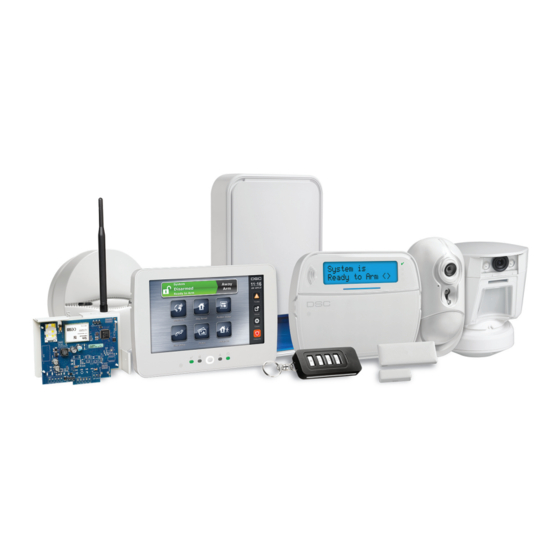
PowerSeries Neo Alarm Controller
WARNING: This manual contains information on limitations regarding product use and function and information on the lim-
itations as to liability of the manufacturer. The entire manual should be carefully read.
V1.2 Reference Manual
Models:
HS2016-4/HS2016/HS2032/HS2064/HS2064 E/
HS2128/HS2128 E
Advertisement
Table of Contents

Related Manuals for DSC HS2128


Summary of Contents for DSC HS2128
- Page 1 PowerSeries Neo Alarm Controller V1.2 Reference Manual Models: HS2016-4/HS2016/HS2032/HS2064/HS2064 E/ HS2128/HS2128 E WARNING: This manual contains information on limitations regarding product use and function and information on the lim- itations as to liability of the manufacturer. The entire manual should be carefully read.
-
Page 2: Safety Instructions For Service Personnel
Safety Instructions for Service Personnel Warning: When using equipment connected to the telephone network, always follow the basic safety instructions provided with this product. Save these instructions for future reference. Inform the end-user of the safety precautions that must be observed when operating this equipment. - Page 3 This alarm system must be installed and used within an environment that provides the pollution degree max 2 and over-voltages category II NON- HAZARDOUS LOCATIONS, indoor only. The equipment is DIRECT PLUG-IN (external transformer) and is designed to be installed, serviced and/or repaired by service persons only;...
-
Page 4: Table Of Contents
Contents 2.0 Safety Instructions for Service Personnel Section 1: Introduction 1.1 About the System Section 2: Installation 2.1 Overview of Installation Process 2.2 Alarm Controller Installation 2.3 Wiring 3.1 Installing Modules Section 4: Configuration 4.1 Basic Configuration Steps 4.2 Using the Keypad 4.3 Enrollment 4.4 Working with Partitions 4.5 Trouble Indicators... - Page 5 7.4 Access Codes 7.5 PGM Programming 7.6 System Lockout 7.7 System Options 7.8 Auto-Arm_Disarm 7.9 Partition and Zone Assignment 7.10 Communications 7.11 Call Directions 7.12 DLS Programming 7.13 Virtual Inputs 7.14 Schedule Programming 7.15 Audio Module Programming 7.16 Wireless Programming 7.17 Alternate Communicators 7.18 Keypad Programming 7.19 Template Programming...
-
Page 6: Section 1: Introduction
Section 1: Introduction 1.1 About the System The PowerSeries Neo alarm panel is a feature-rich, scalable alarm system designed for residential and light commercial use. The alarm panel supports both hardwired and wireless devices. This section lists the features of the alarm panel, avail- able models, and compatible devices. - Page 7 The following alarm controller models are available: HS2016-4 HS2016 HS2032 HS2064 HS2064 E HS2128 HS2128 E Note: Not all models are available in all markets. Model Differences The table below lists the features of each alarm system model. Table 1-1 Model Differences Features HS2128...
- Page 8 Section 1: Introduction Features HS2128 HS2128 HS2064 HS2064 HS2032 HS2016 HS2016-4 Wireless repeaters * Proximity tags Alt Comm. phone #’s User-programmable phone #’s Event buffer 1000 1000 8-zone expander HSM2108 Power supply HSM2300 Power supply/high-current output expander HSM2204 4 8-output expander HSM2208...
- Page 9 Section 1: Introduction 1.1.3 Compatible Devices The following wireless devices and modules are compatible with this alarm controller. Note: On the table below and throughout this document, x in the model number represents the operating frequency of the device as follows: 9 (912-919 MHz), 8 (868MHz), 4 (433MHz). Note: Only models operating in the band 912-919 MHz are UL/ULC listed where indicated.
- Page 10 Section 1: Introduction CO detector CO-12/24 FW-CO1224 12-24SIR CO1224 FW-CO12 Wireless Devices Wireless PG smoke detector PGx926 Wireless PG smoke and heat detector PGx916 Wireless PG CO detector PGx913 Wireless PG PIR motion detector PGx904(P) Wireless PG PIR + camera motion detector PGx934(P) Wireless PG curtain motion detector PGx924...
-
Page 11: Section 2: Installation
Section 2: Installation 2.1 Overview of Installation Process The steps below are provided to assist with the installation of the alarm system. Read over this section to get an overall understanding of the order of installation. Working from this plan can help reduce problems and reduce the overall time required for installation. -
Page 12: Alarm Controller Installation
Section 2: Installation 2.2 Alarm Controller Installation Begin the installation by mounting the alarm controller in the metal enclosure using the stand-offs provided. Optional mod- ules, such as the HSM2108 and HSM2208, can also be mounted in the enclosure. Install hardware in the sequence indicated on the following pages. 2.2.1 Mounting the Enclosure Locate the panel in a dry area, preferably near an unswitched AC power source and the incoming telephone line. - Page 13 Section 2: Installation 2.3.2 Wire Routing for Power & Non-Power Limited All wiring entry points are designated on the diagram by arrows. All circuits are classified UL installation power limited except for the battery leads which are not power limited. A minimum ¼”...
- Page 14 Section 2: Installation Figure 2-2 Wiring Routing (EN50131 only) 2.3.3 Corbus Wiring The RED and BLK Corbus terminals are used to provide power while YEL and GRN are used for data communications. The 4 Corbus terminals of the alarm controller must be connected to the 4 Corbus terminals or wires of each module. The following conditions apply: Corbus should be run with minimum 22 gauge quad, two pair twisted preferred.
- Page 15 HS2064 E 2.0A. short term. Available only with standby battery connected. Not for UL/ULC or EN certified applications. HS2128 HS2128 E HSM2208 AUX: 250mA. Continuous rating. Subtract for each device connected. Subtract the total load on this terminal from the alarm panel AUX/Corbus output.
- Page 16 ***See Corbus Current Calculation Chart. For UL, ULC and Commercial Listed applications, the total standby and alarm current cannot exceed 700mA. Table 3-1 Corbus Current Calculation Chart Item Current (mA) Quantity Total (mA) HS2016-4/HS2016/HS2032/HS2064/HS2064 E/HS2128/HS2128 E HS2LCD HS2ICN HS2LED HS2LCDP HS2ICNP...
-
Page 17: Installing Modules
Item Current (mA) Quantity Total (mA) HSM2HOSTx HSM2955** 3G2080(R)/TL2803G(R)/TL280(R) 125 (PCLINK) Total Corbus Current = *These units draw current from the Corbus to power devices external to the module. This current must be added to the total Corbus current. See manufacturer's specifications for the current draw of each device. ** For HSM2955 current draw refer to HSM2955 installation manual. - Page 18 3.1.1 Zone Expander The main alarm controller has connection terminals for zones 1 to 8. Additional HSM2108 zone expanders may be added to increase the number of zones on the system. Each zone expander consists of one group of 8 zones. At enrollment, the zone expander is automatically assigned to the next available zone slot.
- Page 19 Figure 3-3 HSM2HOSTx Wiring Diagram After you have completed the wiring, reconnect power to the security system. Board current draw: 35mA 3.1.4 Power Supply Wiring The HSM2300/2204 power supply/high-current output module provides up to 1.0A of additional current and can be used to add up to four programmable outputs (HSM2204 only) to the alarm system.
- Page 20 3.1.5 Keypad Wiring To wire a keypad to the alarm controller, remove the keypad backplate (refer to the keypad installation sheet) and connect the RED, BLK, YEL and GRN terminals to the corresponding terminals on the alarm controller. Keypad Zone/PGM Wiring Hardwired devices can be connected to hardwired keypads with inputs (zone) or outputs (PGM).
- Page 21 3.1.8 Zone Wiring Power down the alarm controller and complete all zone wiring. Zones can be wired to supervise normally open devices (e.g., smoke detectors) or normally closed devices (e.g., door con- tacts). The alarm panel can also be programmed for single end-of-line or double end-of-line resistors. Zone programming is done using the following programming sections: [001] selects zone definition [013] Opt [1] for normally closed or EOL;...
- Page 22 Single End-of-Line (SEOL) Resistor When SEOL resistors are installed at the end of a zone loop, the alarm panel detects if the circuit is secure, open, or shorted. The SEOL resistor must be installed at the end of the loop for proper supervision. To enable SEOL supervision, program section [013], options [1] and [2] to OFF.
- Page 23 Note: This option can only be selected if N/C detection devices or contacts are used. Only one N/C contact can be con- nected to each zone. The following table shows zone status under certain conditions for DEOL: Table 3-6 DEOL Loop Status Loop Resistance Loop Status 0 Ω...
- Page 24 Figure 3-10 Bell Wiring The Bell output is supervised and power limited by 2A thermistor. If unused, connect a 1000Ω resistor across Bell+ and Bell- to prevent the panel from displaying a trouble. See "Troubleshooting" on page 47. 3.1.11 Telephone Line Wiring Wire the telephone connection terminals (TIP, Ring, T-1, R-1) to an RJ-31x connector as indicated in the following diagram.
- Page 25 FSA-410BS FSA-410BRT FSA-410BST FSA-410BRS Current ratings for DSC FSA-410 Series: 25mA - 90mA Fire Zone Wiring: 2-wire Smoke Detectors If PGM 2 is programmed for 2-wire smoke detector connection, the detectors must be wired according to the following dia- gram: Figure 3-13 2-Wire Smoke Detector Wiring Note: Additional 2-wire smoke detectors must be connected in parallel as shown above.
- Page 26 3.1.13 CO Detector The following hardwired CO detector models can be used with PowerSeries Neo alarm controllers: Potter Model CO-12/24, UL File E321434 Quantum Model 12-24SIR, UL File E186246 NAPCO Model FW-CO12 or FW-CO1224, UL File E306780 System Sensor Model CO1224, UL File E307195 Note: For multiple unit connections, the leads between CO detectors must be broken.
- Page 27 3.1.14 Ground Wiring Figure 3-15 Ground Installation Note: Using an insulated green wire (minimum 22AWG), connect the EGND terminal on the Corbus and the grounding wire from the building electrical installation to any of the available holes on the back or side of the metal cabinet. See the diagram attached to the cabinet for suggested GND point location and hardware recommendations.
- Page 28 700mA ------ ------ ------ 700mA 500mA 250mA ------ 14Ah * 700mA 470mA ------ 18Ah ------ ------ ------ 300mA* 26Ah ------ ------ ------ 500mA* * use 2 x 7Ah batteries connected in parallel, UL/ULC installations only Battery capacity deteriorates with age and the number of charge/discharge cycles. Replace every 3-5 years. Refer to "Regulatory Approvals"...
-
Page 29: Section 4: Configuration
Section 4: Configuration 4.1 Basic Configuration Steps Once basic installation of the alarm panel is complete, the following general configuration options should be set: create partitions, See "Working with Partitions " on page 32 assign keypads to partitions, see "Keypad Partition Setup " on page 33 assign sirens to partitions, see "Bell/Siren Operation "... - Page 30 Section 4: Configuration Power up sequence – flashes rapidly until the end of the power-up sequence. Firmware indication – flashes during the firmware upgrade process. If the firmware upgrade fails, the LED flashes rap- idly. Trouble indication – Flashes when troubles are present. Troubles are indicated according to the following priority: 1 flash - no keypads enrolled 2 flashes - module supervision trouble 3 flashes - bus low voltage...
-
Page 31: Enrollment
During automatic and manual enrollment, if an attempt is made to enroll more than the maximum number of modules, an error tone sounds and a message is displayed on LCD keypads. Table 4-1 Module Capacity Module HS2016- HS2016 HS2032 HS2064/ HS2128/HS2128 E HS2064 E HSM2108 8 Zone expander HSM2208 8 Output expander Wireless Keypad: HS2LCDRF(P)4... -
Page 32: Working With Partitions
Section 4: Configuration the module is incorrectly wired to the alarm controller the module has exceeded its maximum wire run length the module does not have enough power the module is not enrolled on the wireless receiver Removing Modules Enrolled modules can be deleted from the system via programming section [902]. For instructions, see "[902] Add/Remove Modules"... -
Page 33: Trouble Indicators
Section 4: Configuration 4.4.1 Setting Up a Partition Partitions are added or removed from the system by applying or removing a partition mask via Installer Programming section [200]. The number of available partitions depends on the alarm panel model. See "[200] Partition Mask" on page 111 for more information. - Page 34 Section 4: Configuration 3. Press the [#] and reapeat step 2 for next keypad. When finished programming all keypads, press the [#] key twice to exit programming. Users are assigned partition access rights via the [*][5] menu. 4.6.1 Loaned Partition Setup To loan a keypad to another partition: 1.
- Page 35 Section 4: Configuration 4.6.6 Assign Zones Partition zone assignments are completed using sections [201] - [208] for partitions 1 - 8. Subsections [001 - 016] are then used to enable or disable banks of 8 zones on the partition. 4.6.7 Assign Users Acess [*][5] using the master code, select the desired user code and enter digit 4 to modify the partitions that can accept the user code.
-
Page 36: Alternate Communicator Setup
Section 4: Configuration 4.7 Alternate Communicator Setup The alternate communicator is an optional wireless or ethernet communications device that can be used as a backup to the PSTN connection or as a primary means of communication between the alarm panel and the central monitoring station. The alternate communicator communicates via 3G (HSPA) or Ethernet. -
Page 37: Local Firmware Upgrade
Section 4: Configuration 4.7.5 Supervision Restore If the alarm system experiences a failure to communicate (FTC) with the central monitoring station, it automatically attempts to transmit the event when communications are restored. 4.7.6 Remote Firmware Upgrade Firmware upgrades can be automatically pushed to the alarm panel and modules from Connect 24 or DLS. A message is dis- played on LCD keypads indicating a firmware upgrade is available. - Page 38 Section 4: Configuration 4.9.1 Viewing the Event Buffer The event buffer contains logs of events that have occurred on the alarm system beginning with the most recent. The capa- city of the event buffer is scalable and can hold 500/1000 events (depending on panel model) before rolling over. The buffer displays events according to their time stamp, beginning with the most recent.
-
Page 39: Section 5: System Operation
Section 5: System Operation 5.1 Arming and Disarming The following table describes the various arming and disarming methods available. Table 5-1 Arming/Disarming Methods Method Description for 2 seconds + [Access Code*] Away Arm for 2 seconds + [Access Code*] Stay Arm Night Arm when armed in stay mode [*][1] + [Access Code*] Disarm... -
Page 40: Labels
Section 5: System Operation ! = Alarm N = Not Ready X = Exit Delay E = Entry Delay P = Pre-Alert - = Partition not enabled In the following example, partition 1 is armed, partition 2 is disarmed and ready, partition 3 is disarmed and not ready, par- tition 4 is in alarm, partition 5 is indicating exit delay, partition 6 is in entry delay, partition 7 is in auto-arm pre-alert and par- tition 8 is not enabled. -
Page 41: Annunciation
Section 5: System Operation keypads 8 zone expander modules 8 output expander modules wireless transceiver power supply 4 high-current output module alternate communicator module audio module siren repeater The maximum label size is 14 ASCII characters. See "[801] Keypad Labels" on page 70 for more details. 5.3.5 Event Labels Customizable labels can be created for the following events: Fire alarm... -
Page 42: Keypad Function Keys
Section 5: System Operation 5.4.3 Low Temperature Warning Keypads can be configured to detect low ambient temperature. If the temperature at the keypad drops to 6° C ± 2° C (43° F ± 3°F), the keypad zone goes into alarm. When the temperature rises above 9°... - Page 43 Section 5: System Operation If no Stay/Away zone types are programmed, the alarm system arms in Away mode. Note: Do not use this function with CP-01 installations. [03] Stay Arm Only perimeter zones are armed. Interior zones are bypassed regardless of whether or not delay zones are tripped during the exit delay.
- Page 44 Section 5: System Operation This key only works while the system is armed and requires an access code entry if section [015] option 4 is disabled. [21]-[24] Command Output 1 to 4 This function controls command outputs 1-4 and is the equivalent of entering [*][7][X], where X is 1, 3 or 4. An access code is required to use this function.
-
Page 45: Language Selection
Section 5: System Operation 5.6 Language Selection The keypad can be programmed to display messages and labels in different languages. Perform the following from the Installer Programming menu: 1. Enter installer programming [*][8][installer code] 2. Enter section [000]>[000]. 3. Select a language using the scroll buttons or by entering a hotkey: Table 5-3 Languages [01] –... - Page 46 Section 5: System Operation While in a [*] command menu, use the [*] key to select an option and the [#] key to exit to the previous screen. On an LCD keypad, use the scroll keys to view options. 5.7.1 [*][1] Bypass or Stay/Away/Night Zones The [*][1] command functions differently depending on whether the system is armed or disarmed.
- Page 47 Section 5: System Operation Program Bypass Group To program a bypass group, bypass all desired zones then select Bypass Options > Program Bypass Group. The selected zones are saved to the bypass group. When finished, press [#] to exit. In order to program a bypass group, a master or supervisor code with access to the appropriate partition must be used. Bypass Recall Press [*] while in this menu to bypass the same group of zones that were bypassed the last time the partition was armed.
- Page 48 Section 5: System Operation Troubles may be viewed while the system is armed or disarmed. The system may be programmed to show all troubles while armed or only fire troubles. See section [13] option 3 on page 96 for details. The system can be configured to require a user code to view [*][2] system troubles.
- Page 49 Section 5: System Operation Trouble 05 – Device Faults: [01] Zone 001 - 128: A zone is in fault. Additional information displayed on LCD keypads for the following troubles: Fire Trouble (2-W Smoke, PGX916, PGX926), Freeze (PGX905), Self Test (PGX984), CO (PGX913), and Probe Disconnected (PGX905). Also generated by a short on hardwired zones when DEOL is used or by a wireless supervisory fault.
- Page 50 Section 5: System Operation Trouble 10 – Module Tamper: [01] HSM2HOSTx Tamper. [02] Keypad 01 - 16 Tamper. [04] HSM2108 01 - 15 Tamper. [05] HSM2300 01 - 04 Tamper. [06] HSM2204 01 - 04 Tamper. [08] HSM2208 01 - 16 Tamper. [09] HSM2955 Tamper Trouble 11 –...
- Page 51 Section 5: System Operation This feature can be programmed to require an access code. See "[023] System Option 11" on page 106, option 6 for details. A programmable function key may be configured to display alarms in memory. See "Keypad Function Keys" on page 42 for details.
- Page 52 Section 5: System Operation The Installer and Master codes are system codes. They can be changed but not deleted. The other codes are user-defined and can be added or deleted as necessary. By default, access codes have the same partition and attribute programming as the code used to program them.
- Page 53 Section 5: System Operation Note: Section [019] option 6 must be on to select the Duress Codes attribute. One Time Use Code A one time use code is a user code with the One Time User attribute enabled. This access code enables the user to arm the alarm system an unlimited number of times.
- Page 54 Section 5: System Operation 4 – Remote Access Users with this attribute can access the alarm system remotely via SMS. 7 – Bell Squawk When this option is assigned, the main bell squawks when the alarm system is away armed. For example, use the arm/dis- arm bell squawk attribute to have wireless key access codes squawk the bell, while other codes are silent.
- Page 55 Section 5: System Operation 2. Press the [*] key when prompted to delete the proximity tag. Using an LED/ICON keypad: 1. Press [*][5][Master/Supervisor Code]. 2. Key in a 4-digit user code. 3. Key in [2]. 4. Pass the enrolled tag near the tag reader on the keypad. To increase authentication flexibility, user access can be achieved by entering a valid user code or by swiping a proximity tag.
- Page 56 Section 5: System Operation Event Buffer Menu: [*][6][Master Code] > Event Buffer Keypad: [*][6][Master Code] > [*] This option is used to view system events stored in the event buffer. Events are listed in the order they occurred, starting with the most recent. The time and date are listed for all events. Some events may have a second screen with a description.
- Page 57 Section 5: System Operation Auto-arming can be canceled or postponed only by entering a valid access code during the programmed warning period. When a code is entered, the warning is silenced and auto-arming is canceled or postponed, depending on the auto-arm postpone timer.
- Page 58 Section 5: System Operation Late to Open Menu: [*][6][Master Code] > Late To Open Keypad: [*][6][Master Code] + 09 This function enables or disables the Late to Open option. This option sends a reporting code to the central monitoring sta- tion if the partition has not been disarmed by a programmed time.
- Page 59 Section 5: System Operation Note: For UL/ULC listed installations, do not turn off the keypad sounder. Authorize Firmware Update Menu: [*][6][Master Code] > Authorize Update Keypad: [*][6][Master Code] + 17 This function is used to give authorization to the system to start the firmware upgrade process after all firmware upgrade files for the keypads, HSM2HOST, control panel and alternate communicator have been fully downloaded.
-
Page 60: Sms Command And Control
Section 5: System Operation 5.7.10 [*][9] No-Entry Arming This function is used to arm the alarm system while occupants are on the premises. Pressing [*][9] and then keying in an access code arms the panel without an entry delay on delay type zones and bypasses stay/away and night type zones. After the exit delay, delay 1 and delay 2 type zones behave the same as instant zones. -
Page 61: Visual Verification
Section 5: System Operation Alarm memory request Zone bypass Zone unbypass SMS text messages must be formatted as follows: <function name><space><partition #><space><access code> e.g., Stay Arm partition 1 1234 Once the command is received and executed by the alarm system, the user receives a confirmation text message. Note: Do not use Away Arm if Push to Set [001][072] or Final Door Set [001][016] zones are programmed. -
Page 62: Section 6: Programming
Section 6: Programming 6.1 How to Program This section describes how to view alarm system programming options using the supported keypad types. 6.2 Programming Methods The alarm system can be programmed using the following methods: Table 6-1 Programming Methods Method Description Procedure Template pro-... - Page 63 Section 6: Programming Once the 5 digit number has been entered, the installer cannot exit until all sections are completed. Enter new data and/or press the [#] key to accept the displayed data and proceed to the next section. Changing a single digit, then pressing the [#] key advances to the next section but does not save the changed data.
- Page 64 Section 6: Programming Refer to "[401] DLS/SA Options" on page 127. for details. Note: AC Power must be present for the alarm system to answer incoming calls from DLS. 6.2.3 Installer Programming Installer Programming is used to manually program alarm system options. Access this mode by keying in [*][8][Installer Code].
- Page 65 Section 6: Programming Sections requiring data input, such as phone numbers, display information in a binary format using zone LEDs 1-4 as described in the following chart: Figure 6-2 When a section is entered, the keypad immediately displays the first digit of information programmed. Using the example in Figure 5 above, if zone 1 and 4 are illuminated, the first programmed digit in the section is 9.
- Page 66 Section 6: Programming Table 6-2 HEX Digit Programming Value Enter Telephone Dialer HEX [A] Press [*][1][*] Not supported HEX [B] Press [*][2][*] Simulated [*] key HEX [C] Press [*][3][*] Simulated [#] key HEX [D] Press [*][4][*] Dial tone search HEX [E] Press [*][5][*] Two-second pause HEX [F]...
-
Page 67: Programming Descriptions
Section 6: Programming 6.3 Programming Descriptions This section provides descriptions of all alarm controller options programmable by the installer. 6.3.1 Adding Labels [000] Label Programming Zone and other labels on the alarm system can be customized. Program labels locally or download/upload using DLS. Local label programming is done via a system keypad, as described below. - Page 68 Section 6: Programming To delete a character, use the [<] [>] keys to move the cursor under the character, then press [0]. If any key other than [<] or [>] is pressed before [0], the cursor moves one space to the right and deletes that char- acter.
- Page 69 Section 6: Programming 6. Enter the 3-digit number corresponding to a word (see "Word Library" on page 221) or use the scroll keys [<][>] to view words in the library. 7. Press [*] to select the word. 8. To add another word, repeat the above procedure from step 4. 9.
- Page 70 Section 6: Programming [601]-[604] Schedule Labels Use this section to program custom labels for command output schedules. These labels are used to identify schedules for PGM command outputs 1-4. The maximum label size is 16 characters. See "Programming" on page 62 for specific instruc- tions on how to program labels.
- Page 71 Section 6: Programming Delay 1 – Commonly assigned to primary points of entry. Follows entry delay 1 and exit delay timers (section [005]). Arming the alarm system starts the exit delay timer. After the exit delay has expired, opening the door starts the entry delay timer. During entry delay, the keypad buzzer prompts the user to disarm the system.
- Page 72 Section 6: Programming Day Zone – Commonly used in areas where immediate notification of entry is desired. When disarmed, tripping this zone activates the keypad buzzer but does not log or report the event. When armed, tripping this zone activates the siren then logs and reports the event.
- Page 73 Section 6: Programming Auto Verify Fire – (Hardwired smoke detectors) When the zone is activated, a 30-second delay begins but no fire alarm sounds. If the same zone is activated again up to 60 seconds after the delay expires, the alarm is triggered immediately. If the same zone is activated after 60 seconds, the entire sequence begins again.
- Page 74 Section 6: Programming 24-Hour Sprinkler – Instant alarm when activated, audible alarm at default. 24-Hour Flood – Instant alarm when activated, audible alarm at default. 24-Hour Latching Tamper – Instant alarm when activated, audible alarm at default. The alarm system cannot be armed until Installer Programming is entered after the zone is restored.
- Page 75 Section 6: Programming With an audible alarm active, using the keyswitch when disarmed is the same as entering an access code at the keypad. Activating this zone type during the first 30 seconds of a delayed fire alarm is the same as pressing a key at the keypad (the 90 second delay starts).
- Page 76 Section 6: Programming Bell Steady – ON: Siren output is steady when in alarm. OFF: Siren output pulses when in alarm. Door Chime – ON: The keypad chimes when the zone is open and when the zone is secured. OFF: The zone does not chime. Bypass Enabled –...
- Page 77 Section 6: Programming 2-Way Audio Attribute – ON: Panel is able to initiate a 2 way audio session. OFF: Only the microphone turns on, initiating a a Listen-in only session. The speaker remains off. Hold Up Verification – ON: An alarm from zones of this type can contribute to a verified hold up alarm. Use this attribute with Panic and Hold Up zones. OFF: An alarm from zones of this type does not contribute to a verified hold up alarm.
- Page 78 Section 6: Programming Note: For UL installations, the Entry Delay plus the Communications Delay must not exceed 60 seconds. Entry Delay 1: This value determines the entry delay time for delay 1 type zones. Valid entries are 001 to 255 seconds. Entry Delay 2: This value determines the entry delay time for delay 2 type zones.
- Page 79 Section 6: Programming [001] – Installer Code This code is used by the installer to gain access to Installer Programming [*][8]. Users with this access code have access to all levels of system programming. Note: For EN50131-1 approved installations the installer code cannot change the master code or any other level 3 codes. [002] –...
- Page 80 Section 6: Programming 6.3.6 [009] PGM Types The output types described in this section can be assigned to alarm controller and output expander module PGMs. Each alarm controller supports up to 2 or 4 PGMs and can be expanded using HSM2208 output expander and HSM2204 High- Current output modulemodules.
- Page 81 Section 6: Programming The 2-wire smoke detector input creates an instant and latching alarm. 109 – Courtesy Pulse Courtesy pulse causes an output to activate for the entry and exit times, plus 2 minutes. This option is typically used to activ- ate a courtesy light near the exit door for the duration of the entry/exit times.
- Page 82 Section 6: Programming 129 – Partition Status Alarm Memory This feature is intended to be used on a keyswitch plate, with a light controlled by this PGM to indicate system status. When the partition is armed, the output activates (steady) at the: beginning of exit delay end of exit delay.
- Page 83 Section 6: Programming on the system: Fire (Fire Key, Fire Zones) Panic (Panic Key and Panic Zones) Burglary (Delay, Instant, Interior, Stay/Away and 24-hour Burglary Zones) Opening/Closing Events Zone Auto-Bypass. (Please see 08 – Zone Auto-Bypass for details). Medical (Medical Key, Medical and Emergency Zones) Burglary Verified Opening After Alarm Emergency Alarm...
- Page 84 Section 6: Programming Priority (Gas, Heat, Sprinkler and 24-Hour Latching Zones) Holdup (Holdup zones) Output follows pulse timer (See "[008] PGM Timer Programming" on page 79). Duress Emergency CO Alarm Fire Supervisory Fire trouble This output does not activate during pre-alert or delays. In the armed state, the output deactivates only once the system is disarmed.
- Page 85 Section 6: Programming 175 – Bell Status and Programming Access Output This PGM activates when the siren, Installer Programming mode or DLS/SA is active. It deactivates after bell timeout, when Installer Programming is exited or when DLS/SA programming is disconnected. 176 –...
- Page 86 Section 6: Programming Burglary Alarm ON: Burglary alarm (Delay, Instant, Interior, Stay/Away, Night, Interior Delay, Instant Stay/Away, Day, 24-hour Burglary) activates the main siren. OFF: Burglary alarm does not activate the main siren. 24-Hour Flood Alarm ON: Main bell activates in the event of a 24-Hour Flood alarm. OFF: Main bell does not activate in the event of a 24-Hour Flood alarm.
- Page 87 Section 6: Programming 02 – Timed Output ON: output remains active until the PGM output timer expires. OFF: output remains active until the buzzer condition ends. 09 – Entry Delay ON: activates on entry delay. OFF: does not activate on entry. 10 –...
- Page 88 Section 6: Programming 121-124 – Command Output 1-4 01 – True Output/Inverted ON: deactivated during normal operation, activated when triggered. OFF: activated during normal operation, deactivated when triggered. 02 – Timed Output / Latched Output ON: output remains active until the PGM output timer expires. OFF: output remains active until an access code has been entered.
- Page 89 Section 6: Programming 05 – Panic Alarm ON: activates with panic alarm, [P] key, panic zones. OFF: does not activate with panic alarm. 06 – Burglary Alarm ON: activates with burglary alarm. OFF: does not activate with burglary alarm. 07 – Open/Close ON: activates with opening or closing.
- Page 90 Section 6: Programming 05 – Loss of Clock ON: activates on loss of clock trouble condition. OFF: does not activate on loss of clock trouble condition. 06 – DC Trouble ON: activates if a panel low or no battery trouble is detected, or if an HSM2204/2300 1-4 low or no battery trouble is detected.
- Page 91 Section 6: Programming 12 – RF Delinquency ON: activates if any of the following RF delinquency troubles is detected: zone 001 – 128 keypad 01 – 16 siren 01 – 16 repeater 01 – 08 OFF – does not activate if an RF delinquency condition is present. 13 –...
- Page 92 Section 6: Programming OFF – does not activate if a not networked trouble condition is present. 156 – Latched System Event 01 – True Output/Inverted ON: deactivated during normal operation. Activated when triggered. OFF: activated during normal operation. Deactivated when triggered. 02 –...
- Page 93 Section 6: Programming OFF: does not activate on fire trouble condition. 15– CO Alarm ON: activates on CO alarm. OFF: does not activate on CO alarm. 157 – System Tamper 01 – True Output/Inverted ON: deactivated during normal operation. Activated when triggered. OFF: activated during normal operation.
- Page 94 Section 6: Programming 176 – Remote Operation 01 – True Output/Inverted ON: deactivated during normal operation. Activated when triggered. OFF: activated during normal operation. Deactivated when triggered. 184 – Open After Alarm 01 – True Output/Inverted ON: deactivated during normal operation. Activated when triggered. OFF: activated during normal operation.
- Page 95 Section 6: Programming 09-16 – Zone Terminals 1-8 ON: zones associated with terminals 1-8 are enabled for zone follower operation. OFF: zones are not enabled for zone follower operation. 6.3.8 [011] PGM Configuration Options This section is used to configure PGM types that offer multiple options. [001]-[164] Select PGM The following options may be selected for each PGM: Zone Follow PGM By Zone...
- Page 96 Section 6: Programming Remote Lockout Duration This programming option determines how long the remote lockout lasts. If the system cold starts while in remote lockout, the lockout restarts for the programmed duration. Valid entries are 001 to 255 minutes. Entering 000 disables remote lockout. 6.3.10 System Options [013] System Option 1 1 –...
- Page 97 Section 6: Programming OFF: The event buffer continues to log events to the buffer even after the event has gone into swinger shutdown. 8 – Temporal Three Fire Signaling ON: All fire bells sound in the temporal three pattern. Cadence is as follows: (500ms ON, 500ms OFF, 500ms ON, 500ms OFF, 500ms ON, 1.5 sec.
- Page 98 Section 6: Programming [015] System Option 3 1 – [F] Key Enabled ON: Pressing and holding the [F] key for 2 seconds triggers a Fire alarm. OFF: The [F] key does not sound or report an alarm when pressed. Note: Use only for residential fire installations. 2 –...
- Page 99 Section 6: Programming [016] System Option 4 1 – AC Trouble Display ON: If AC power fails, the condition is reported to the monitoring station and is indicated as a trouble condition on the system keypads. OFF: If AC power fails, the condition is reported, but the Trouble light on the system keypads is off. The trouble is displayed in [*][2].
- Page 100 Section 6: Programming OFF: The tamper switches on all keypads do not generate tamper alarms. Note: If this option is used, all keypads should be properly installed and secured (tamper restored) before enabling the option. Note: Must be ON for UL/ULC commercial burglary listed installations. [017] System Option 5 1 –...
- Page 101 Section 6: Programming savings clock adjust. Daylight Savings Time programming should not conflict with the Auto-arm and Test Transmissions pro- gramming. OFF: The alarm system makes no automatic time adjustments for Daylight Saving time. 7 – Silence Chime During Quick Exit Delay ON: Door chime does not sound during quick exit.
- Page 102 Section 6: Programming 6 – Not Used 7 – Exit Delay Restart ON: Opening a delay zone door after it has already been opened and closed during an exit delay restarts the exit delay timer. Further openings and closings do not restart the timer. OFF: Delay zone openings and closings do not restart the exit delay.
- Page 103 Section 6: Programming 8 – Reset After Zone Activation ON: Only a police code\sequential detection alarm requires a remote reset once the partition has been disarmed. OFF: Any burglary alarm requires a remote reset once the partition has been disarmed. [020] System Option 8 1 –...
- Page 104 Section 6: Programming While the system is locked out, the only options available are [*][3], [*][6], [*][7], and [*][8]. Accessing [*][8] Installer Pro- gramming unlocks the alarm system. The system continues to function (alarms, tampers, etc) while the system is locked out. Lock out follows both transmission and bell delays.
- Page 105 Section 6: Programming [021] System Option 9 1 – Trouble Display ON: If the panel is both armed and keypad blanking is active, when a trouble is present the keypad trouble LED will remain off . When the system is disarmed, or if blanking is removed, the trouble LED will be active if a trouble is present. OFF: The trouble LED will turn off when keypad blanking is active only while armed.
- Page 106 Section 6: Programming 2 – Not Used 3 – Not Used 4 – Transmission Counter in Hours ON: The alarm system sends a test transmission after the programmed number of hours in the test transmission cycle (Sec- tion [377], Option 003). OFF: The alarm system sends a test transmission after the programmed number of days.
- Page 107 Section 6: Programming 4 – Access Code Required for [*][1] ON: When using the [*][1] Bypass Zones command, an access code must be input before zones are bypassed. OFF: An access code is not required to bypass zones using [*][1]. 5 –...
- Page 108 Section 6: Programming OFF: The alarm system does not send a real-time clock request to the alternate communicator. Local time setting is used as the system time. 6 – Not Used 7 – Brownout Detection ON: If AC drops below the acceptable level, the alarm system generates an AC trouble. OFF: AC Brownout detection is disabled.
- Page 109 Section 6: Programming OFF: I.D. tone is disabled. 6 – Tone Generated-2100Hz ON: 2100 Hz I.D. tone. OFF: 1300 Hz I.D. tone. 7 – 1 Hour DLS Window ON: When DLS access is enabled ([*][6] option 5 ON), Installer Programming is accessible through DLS or the [*][8] menu only once during a 1-hour window.
- Page 110 Section 6: Programming Mode Description 001 Police Code The burglary verification timer operates in minutes. 002 Cross Zoning The burglary verification timer operates in seconds. The first alarm in the sequence does not log or communicate the alarm or activate the bell. 003 Sequential The burglary verification timer operates in minutes.
- Page 111 Select options 01-08 to enable or disable partitions. Partition 1 is always enabled. Partitions 2 to 8 are selectable. The number of available partitions depends on the model, as shown below: Model Zones Partitions HS2128/HS2128 E HS2064/HS2064 E HS2032 HS2016 HS2016-4 [201]-[208] Partition Zone Assignment Zones can be assigned to any partition.
- Page 112 Section 6: Programming 57-64 121-128 All zones assigned to a partition are supervised and operate according to the zone type programmed. If a zone is not assigned to a partition, it is not supervised and all activity on the zone is ignored by the system. [300] Panel/Receiver Communication Paths This section is used to select the path of communications between the alarm system and the central station.
- Page 113 Section 6: Programming HEX F ([*] [6] [*]) - represents the end of the Phone Number (everything after F is ignored). Pressing [#] in these sections exits and saves the entire phone number. The alarm system does not attempt to communicate using PSTN if no phone number is programmed. [304] Call Waiting Cancel String Use this section to program a string that, when pressed, disables call waiting on a phone line.
- Page 114 Section 6: Programming 7 – Burglary Not Verified When using Cross Zoning, this reporting code is sent if the cross zone timer is initiated by the first cross zone alarm, but is not verified by a second alarm before the timer expires. 8 –...
- Page 115 Section 6: Programming 7/8 – Keyswitch Opening/Closing This reporting code is transmitted when a keyswitch zone is used to arm or disarm the system. [202] Open/Close Events 2 1 – Automatic Closing This reporting code is transmitted when a partition is automatically armed or schedule armed and uses the Opening call dir- ection group.
- Page 116 Section 6: Programming [302] Panel Events 2 1/2 – Bell Circuit Trouble/Restore This reporting code is transmitted when a bell trouble condition occurs or is restored on the system.This reporting code is sent to the System Maintenance call direction group. 3/4 –...
- Page 117 Section 6: Programming 3/4 – DLS Lead In/Lead Out The DLS Lead In reporting code is sent: after DLS communication has been successfully established, but before the alarm system calls back the down- loading computer. This code is only transmitted when call back is enabled. on user-initiated call-up.
- Page 118 Section 6: Programming 5/6 – Module Battery Absent/Restore These reporting codes are transmitted when a module’s battery is detected as absent or restored. These reporting codes are sent to the System Maintenance call direction group. [332] Module Events 2 1/2 – Module Low Voltage Trouble/Restore Sent when module voltage drops below acceptable levels or is restored.
- Page 119 Section 6: Programming [361] Wireless Device Events 1/2 – Wireless Device AC Failure/Restore These options are used to enable wireless device AC failure/restore reporting codes. These reporting codes are sent when a wireless device experiences an AC failure/restore. 3/4 – Wireless Device Low Battery Trouble/Restore These options are used to enable wireless device low battery trouble/restore reporting codes.
- Page 120 Section 6: Programming [001] Maintenance Events/Restores (all troubles except tampers) These options control which receiver paths are enabled for maintenance events. To assign a maintenance event to a receiver, select from the following list: [01] Receiver 1 [02] Receiver 2 [03] Receiver 3 [04] Receiver 4 [002] Test Transmissions...
- Page 121 Section 6: Programming [002] Tampers (Including System Tampers)/ Restore These options control which receiver paths are enabled for Partition 1-8 Tamper and Restore event reporting codes. To assign an event to a receiver, select one of the following options: [01] Receiver 1 [02] Receiver 2 [03] Receiver 3 [04] Receiver 4...
- Page 122 Section 6: Programming Maintenance Troubles/Restores This value defines the number of times the same system Maintenance (trouble) type event occurs before going into swinger shutdown. Fire troubles follow the Maintenance Swinger Shutdown variable. [002] – Communication Delays Transmission Delay (seconds) This value defines the delay before an alarm is transmitted.
- Page 123 Section 6: Programming [004] – Periodic Test Transmission Time of Day Enter a 4-digit time using the 24-hour clock format (HH:MM). Valid entries are from 00 to 23 for the hours (HH) and 00 to 59 for the minutes (MM). To disable the test transmission time of day, enter [9999] in this section.
- Page 124 Section 6: Programming OFF: Zone restore reporting codes are transmitted when the zone is physically restored. If zones are still active when the sys- tem is disarmed, the restore codes are transmitted when the system is disarmed. 3 – Pulse Dialing ON: The alarm system dials telephone numbers using pulse (rotary) dialing.
- Page 125 Section 6: Programming Each day programmed in the counter represents one day plus the time it takes for the partition to reach midnight. To disable this feature, program 000 in section [377]>[002] option 5. [381] Communicator Option 2 1 – Keypad Ringback ON: When the Opening After Alarm reporting code is successfully transmitted to a programmed telephone number, the keypad emits a series of 8 beeps to confirm to the occupant that the code was sent and received.
- Page 126 Section 6: Programming 5 – Alternate Communicator Enable/Disable ON: The system communicates using the alternate communicator. All related programming options, reporting and super- vision are enabled when programmed via PC-Link2. OFF: The alternate communicator and all associated programming functionality are disabled. The auto time update feature is disabled.
- Page 127 Section 6: Programming Receiver 3 uses the same format programmed for Receiver 2. OFF: Receiver 3 is independent and will communicate if a number and format are programmed. 4 – Receiver 4 Backup Option ON: Receiver 4 backs up Receiver 3. Receiver 4 is only used if an FTC event is detected on Receiver 3. Receiver 4 uses the same format programmed for Receiver 3.
- Page 128 Section 6: Programming duration of the double call timer (section [405]), the alarm system answers on the first ring. OFF : Incoming calls are not answered using the double call routine unless the user enables the DLS window. Note: This feature controls the DLS window for PSTN connections only. 2 –...
- Page 129 Section 6: Programming If cellular or IP paths are used for the DLS connection, a pre-programmed number of unsuccessful attempts causes a 1-hour DLS lockout. Number of attempts is programmed in section [012]. [404] DLS/SA Panel ID This 10-digit hexadecimal code identifies the alarm system to the downloading computer. [405] PSTN Double Call Timer Use this section to program the amount of time that can elapse between the first and second call when using Double Call downloading.
- Page 130 Section 6: Programming OFF: The alarm system does not automatically call the downloading computer when the system programming changes. [002] Periodic DLS Days This section is used to program the number of days between periodic DLS downloads. Valid entries are from 001 to 255 days.
- Page 131 Section 6: Programming [711]-[714] Holiday Schedules Use this section to program holiday schedules. During holiday schedules, other scheduled events do not occur. Enter sec- tion 711 to 714 for holiday group 1 to 4. Each of the four available holiday groups can have up to 99 holiday schedules programmed. [001]-[099] Holiday Dates 1-99 Program holiday dates in the following format: MMDDYY MM valid entries are 01 to 12...
- Page 132 Section 6: Programming [851] Alternate Communicator Programming See the alternate communicator installation manual for programming instructions. [860] Display Keypad Slot Number The 2-digit slot number of the keypad being used is displayed in this read only section. [861]-[876] Keypad Programming Use section [861] to [876] to configure keypads 1 to 16.
- Page 133 Section 6: Programming [001]-[016] keypads [101]-[115] 8-zone expansion module [201] 8-output expansion module [460] Alternate Communicator [461] HSM2Host module [501]-[504] 1A power supply module [521]-[524] high-current output modules 1-4 [901] Installer Walk Test Mode Enable/Disable This mode tests the operation of each detector in the system. Enter section [901] to initiate a walk test. While in Walk Test mode, the Ready, Armed, and Trouble LED's on the keypad flash to indicate that the test is active.
- Page 134 Section 6: Programming 2. When prompted, key in the serial number of the module found on the PCB. An error tone is sounded if an invalid serial number is used. 3. To cancel enrollment of a module, press [#]. [002] – Module Slot Assignment (LED, LCD, ICON) This section is used to change the slot number a module is enrolled in.
- Page 135 Section 6: Programming 2. Press [*] to select the module type then scroll to the specific module you want to confirm. Press [*] to enter Confirmation mode. The module’s serial number and slot number are displayed on the keypad and the status LEDs on the device flash. This continues until confirmation mode for the device is exited via the [#] key.
- Page 136 Section 6: Programming [001]-[128] Placement Test Zones 1-128 Test wireless devices individually by zone (LCD keypads only). [521]-[528] Placement Test Repeaters 1-8 Test each enrolled wireless repeater (LCD keypads only). [551]-[566] Placement Test Sirens 1-16 Test each enrolled wireless siren (LCD keypads only). [601]-[632] Placement Test Wireless keys 1-32 Test individual wireless keys.
- Page 137 Section 6: Programming [010] – High Current Output Battery Enables and disables the high-current battery charge option for HSM2204 1-4. [020] – 1A Power Supply Battery Enables and disables the high-current battery charge option for HSM2300 1-4. 6.3.22 Defaults [989] Default Master Code This section is used to default the master code to the factory default.
-
Page 138: Section 7: Programming Worksheets
Section 7: Programming Worksheets Note: listed options are required for EN 50131 Compliant Installations. 7.1 Label Programming [000] Label Programming Description on page 67 [000] – Language Selection (2-digit decimal; Default: 01) 01 – English 06 – Dutch 11 – Swedish 16 –... - Page 139 Section 7: Programming Worksheets 073: 074: 075: 076: 077: 078: 079: 080: 081: 082: 083: 084: 085: 086: 087: 088: 089: 090: 091: 092: 093: 094: 095: 096: 097: 098: 099: 100: 101: 102: 103: 104: 105: 106: 107: 108: 109: 110: 111:...
- Page 140 Section 7: Programming Worksheets 002 – Partition 1 Command Output 2: (2 X 14 ASCII) 003 – Partition 1 Command Output 3: Descriptions on page 69 004 – Partition 1 Command Output 4: 202 – Partition 2 Command Output 001 – Partition 2 Command Output 1: Labels (2 X 14 ASCII) 002 –...
- Page 141 Section 7: Programming Worksheets 602 – Schedule 2 Label (1 X 16 ASCII): 603 – Schedule 3 Label (1 X 16 ASCII): 604 – Schedule 4 Label (1 X 16 ASCII): [000] 801 – Keypad Labels (1 X 14 ASCII) Description on page 70 001 –...
- Page 142 Section 7: Programming Worksheets 004 – Power Supply 4 Label: [000] 810 – HSM2204 High-Current Output Supply Label 001 – High-Current Output Supply 1 Label: (1 X 14 ASCII) 002 – High-Current Output Supply 2 Label: 003 – High-Current Output Supply 3 Label: Description on page 70 004 –...
-
Page 143: Zone Setup
Section 7: Programming Worksheets 7.2 Zone Setup [001] [001 - 128] Zone Type Available Zone Types Default = 000 Description on page 70 * Not UL evaluated 000 – Null Zone 018 – 24-Hour Bell/Buzzer 001 – Delay 1 023 – 24-Hour Supervisory 002 –... - Page 144 Section 7: Programming Worksheets CP-01 Delay 1 CP-01 Delay 2 CP-01 Instant CP-01 Interior Interior CP-01 Stay/Away CP-01 Delay Stay/Away Delayed 24-Hour Fire Standard 24- Hour Fire CP-01 Instant Stay/Away CP-01 Interior Delay Day Zone Night Zone CP-01 CP-01 Final Door Set CP-01 CP-01 24-Hour Burglary...
- Page 145 Section 7: Programming Worksheets CP-01 CP-01 24-Hour Holdup CP-01 CP-01 24-Hour Panic CP-01 24-Hour Heat CP-01 CP-01 24-Hour Medical CP-01 24-Hour CP-01 Emergency CP-01 CP-01 24-Hour Sprinkler CP-01 CP-01 24-Hour Flood CP-01 24-Hour Latching CP-01 Tamper 24-Hour Non- Alarm CP-01 24 Hour High CP-01 Temperature...
-
Page 146: System Times
Section 7: Programming Worksheets 7.3 System Times [005] System Times 000 – System Area Bell Cutoff (Default: 004 minutes): Description (3-Digit Decimal) Bell Delay Time (Default: 000 minutes): on page 77 Burglary Verification Timer (Default: 060 minutes): Holdup Verification Timer (Default: 008 hours): Zone Loop Response Time (Default: 025 x 10ms): Automatic Clock Adjust (Default: 060 seconds): 001 –... -
Page 147: Access Codes
Section 7: Programming Worksheets Entry Delay 2: See partition 1 for defaults Exit Delay: Settle Delay: 008 – Partition 8 Timer Entry Delay 1: Entry Delay 2: See partition 1 for defaults Exit Delay: Settle Delay 900 - Bell Delay Partition Mask 1 2 3 4 5 6 7 8 Default: All partitions on Y Y Y Y Y Y Y... - Page 148 Section 7: Programming Worksheets [001 – 164] PGM Partition Assignment 1 2 3 4 5 6 7 8 Default: Partition 1 on. All others off Y N N N N N N N Description on page 86 [008] [000 - 164] PGM Timer Programming [000] –...
- Page 149 Section 7: Programming Worksheets [008] [000 - 164] PGM Timer Programming 109 – PGM 109: 110 – PGM 110: 111 – PGM 111: 112 – PGM 112: 113 – PGM 113: 114 – PGM 114: 115 – PGM 115: 116 – PGM 116: 117 –...
- Page 150 Section 7: Programming Worksheets [009] [001] - [164] PGM Types (3-Digit Decimal) Valid Range: 001-216 001 Default: 121 Command Output 1 002 Default: 156 System Event 003 - 164 Default: 101 Burg and Fire Bell Follower Description on page 80 001 –...
- Page 151 Section 7: Programming Worksheets [009] [001] - [164] PGM Types 121 – PGM 121: 122 – PGM 122: 123 – PGM 123: 124 – PGM 124: 125 – PGM 125: 126 – PGM 126: 127 – PGM 127: 128 – PGM 128: 129 –...
- Page 152 Section 7: Programming Worksheets [010] [000 - 164] PGM Attributes R 01 – True Output 120 – Away Armed No Bypass R 01 – True Output o 02 – Timed Output R Schedule 001 121 – Command Output 1 R 03 – Code Required R 01 –...
- Page 153 Section 7: Programming Worksheets [010] [000 - 164] PGM Attributes R 01 – True Output o 02 – Timed Output R 04 – Service Required R 05 – Loss of Clock R 06 – DC Trouble R 07 – Bus Voltage R 08 –...
- Page 154 Section 7: Programming Worksheets [010] [000 - 164] PGM Attributes R 01 – True Output 166 – Prox Used Part o 02 – Timed Output R 01 – True Output 175 – Bell Prog Access R 01 – True Output 176 –...
- Page 155 Section 7: Programming Worksheets [010] PGM Attribute Assignment: 017 – PGM 17: 018 – PGM 18: 019 – PGM 19: 020 – PGM 20: 021 – PGM 21: 022 – PGM 22: 023 – PGM 23: 024 – PGM 24: 025 –...
- Page 156 Section 7: Programming Worksheets [010] PGM Attribute Assignment: 153 – PGM 153: 154 – PGM 154: 155 – PGM 155: 156 – PGM 156: 157 – PGM 157: 158 – PGM 158: 159 – PGM 159: 160 – PGM 160: 161 –...
- Page 157 Section 7: Programming Worksheets [011] PGM Config. Options page 95 Description on Zone Follower by Zone Prox. Used Schedule (000-128; Default 000) (000-095; Default 000) (000-004; Default 000) PGM 45 HSM2208 #2 PGM 46 PGM 47 PGM 48 PGM 49 PGM 50 PGM 51 PGM 52...
- Page 158 Section 7: Programming Worksheets [011] PGM Config. Options page 95 Description on Zone Follower by Zone Prox. Used Schedule (000-128; Default 000) (000-095; Default 000) (000-004; Default 000) PGM 77 PGM 78 HSM2208 #6 PGM 79 PGM 80 PGM 81 PGM 82 PGM 83 PGM 84...
- Page 159 Section 7: Programming Worksheets [011] PGM Config. Options page 95 Description on Zone Follower by Zone Prox. Used Schedule (000-128; Default 000) (000-095; Default 000) (000-004; Default 000) PGM 109 HSM2208 #10 PGM 110 PGM 111 PGM 112 PGM 113 PGM 114 PGM 115 PGM 116...
-
Page 160: System Lockout
Section 7: Programming Worksheets [011] PGM Config. Options page 95 Description on Zone Follower by Zone Prox. Used Schedule (000-128; Default 000) (000-095; Default 000) (000-004; Default 000) PGM 141 HSM2208 #14 PGM 142 PGM 143 PGM 144 PGM 145 PGM 146 PGM 147 PGM 148... -
Page 161: System Options
Section 7: Programming Worksheets (Range: 001-255; Default 000) Keypad Lockout Duration: Note: For installations minimum programmed duration of 2 minutes. Remote Lockout: (Range: 003-255; Default 006) Remote Lockout Duration: (Range: 001-255; Default 060) 7.7 System Options [013] System Options 1 Description on page 96 o 1 –... - Page 162 Section 7: Programming Worksheets o 8 – TLM Audible When Armed [016] System Options 4 Description on page 99 R 1 – AC Trouble Display o 2 – AC Trouble Light Flashes R 2 – AC Trouble Light Flashes o 3 – Keypad Blanking R 3 –...
- Page 163 Section 7: Programming Worksheets R 7 – Exit Delay Restart CP-01 o 8 – AC Fail Trouble Beeps R 8 – AC Fail Trouble Beeps [019] System Options 7 Description on page 102 o 1 – Audible Wireless Zone Fault o 2 –...
- Page 164 Section 7: Programming Worksheets o 6 – Armed Display o 7 – Open Cancels Arming R 7 – Open Cancels Arming o 8 – Audible Exit Delay for Stay Arm [022] System Options 10 Description on page 105 o 1 – [F] Key Option o 2 –...
-
Page 165: Auto-Arm_Disarm
Section 7: Programming Worksheets o 4 – Tampers Inhibit Arming o 5 – Real Time Clock Option o 6 – Not Used o 7 – Brownout Detection Enabled/Disabled o 8 – DLS Disconnect [025] System Options 13 Description on page 108 o 1 –... - Page 166 Section 7: Programming Worksheets Sunday: Thursday: (4-digit HH:MM) Monday: Friday: Default: 9999 Tuesday: Saturday: Wednesday: 24-Hour: 002 – Partition 1 Auto-Disarm Times: Sunday: Thursday: (4-digit HH:MM) Default: 9999 Monday: Friday: Tuesday: Saturday: Wednesday: Holiday 1: o On R Off 003 – Partition 1 Auto-Disarming Holiday Schedule: Holiday 2: o On R Off (3-digit decimal) Holiday 3: o On R Off...
- Page 167 Section 7: Programming Worksheets Partition 3 Auto-Arm/Disarm [153] 24-Hour: 001 – Partition 3 Auto-Arming Times: (4-digit HH:MM) Sunday: Thursday: Default: 9999 Monday: Friday: Tuesday: Saturday: Wednesday: 002 – Partition 3 Auto-Disarm Times: 24-Hour: (4-digit HH:MM) Sunday: Thursday: Monday: Friday: Default: 9999 Tuesday: Saturday: Wednesday:...
- Page 168 Section 7: Programming Worksheets 006 – Partition 4 No Activity Arming Timer (Default: 000): 007 – Partition 4 No Activity Arming Pre-Alert Timer (Default: 001): Partition 5 Auto-Arm/Disarm [155] 001 – Partition 5 Auto-Arming Times: 24-Hour: Sunday: Thursday: (4-digit HH:MM) Monday: Friday: Default: 9999...
- Page 169 Section 7: Programming Worksheets 004 – Partition 6 Auto-Arming Pre-Alert (Default: 004): 005 – Partition 6 Auto-Arming Postpone Timer (Default: 000): 006 – Partition 6 No Activity Arming Timer (Default: 000): 007 – Partition 6 No Activity Arming Pre-Alert Timer (Default: 001): Partition 7 Auto-Arm/Disarm [157] 001 –...
-
Page 170: Partition And Zone Assignment
Section 7: Programming Worksheets Holiday 3: o On R Off Holiday 4: o On R Off 004 – Partition 8 Auto-Arming Pre-Alert (Default: 004): 005 – Partition 8 Auto-Arming Postpone Timer (Default: 000): 006 – Partition 8 No Activity Arming Timer (Default: 000): 007 –... - Page 171 Section 7: Programming Worksheets 015 – 113-120 o o o o o o o o 015 – 113-120 o o o o o o o o 016 – 121-128 o o o o o o o o 016 – 121-128 o o o o o o o o [203] Partition 3 Zone Assignment [204] Partition 4 Zone Assignment...
-
Page 172: Communications
Section 7: Programming Worksheets 016 – 121-128 o o o o o o o o 016 – 121-128 o o o o o o o o [207] Partition 7 Zone Assignment [208] Partition 8 Zone Assignment Bit 1 2 3 4 5 6 7 8 Bit 1 2 3 4 5 6 7 8 001 –... - Page 173 Section 7: Programming Worksheets o Alt Comm Auto Routing o Alt Comm Rec 1 o Alt Comm Rec 2 o Alt Comm Rec 3 o Alt Comm Rec 4 R PSTN-Phone Line 004 – Receiver 4: o Alt Comm Auto Routing o Alt Comm Rec 1 o Alt Comm Rec 2 o Alt Comm Rec 3...
- Page 174 Section 7: Programming Worksheets RRRRRRoo RRRRRRoo RRRRRRoo RRRRRRoo RRRRRRoo 1 2 3 4 5 6 7 8 1 2 3 4 5 6 7 8 1 2 3 4 5 6 7 8 1 2 3 4 5 6 7 8 1 2 3 4 5 6 7 8 RRRRRRoo RRRRRRoo...
- Page 175 Section 7: Programming Worksheets RRRRRRoo RRRRRRoo RRRRRRoo RRRRRRoo RRRRRRoo 1 2 3 4 5 6 7 8 1 2 3 4 5 6 7 8 1 2 3 4 5 6 7 8 1 2 3 4 5 6 7 8 1 2 3 4 5 6 7 8 RRRRRRoo RRRRRRoo...
- Page 176 Section 7: Programming Worksheets [308] Event Reporting Description on page 113 R 1 – Automatic Closing 202 – Open/Close Events 2 R 2 – Automatic Disarm R 3 – Auto Arm Cancellation/Postpone R 1 – Late to Close 211 – Miscellaneous Open/Close R 2 –...
- Page 177 Section 7: Programming Worksheets [308] Event Reporting Description on page 113 R 1 – Installer Lead IN R 2 – Installer Lead OUT R 3 – DLS Lead IN R 4 – DLS Lead OUT R 5 – SA Lead IN R 6 –...
- Page 178 Section 7: Programming Worksheets [308] Event Reporting Description on page 113 R 1 – Module AC Trouble R 2 – Module AC Trouble Restore R 3 – Module Battery Trouble 331 – Module Events 1 R 4 – Module Battery Trouble Restore R 5 –...
-
Page 179: Call Directions
Section 7: Programming Worksheets [308] Event Reporting Description on page 113 R 1 – Alt. Comm Receiver 1 Supervision Failure R 2 – Alt. Comm Receiver 1 Supervision Restore R 3 – Alt. Comm Receiver 2 Supervision Failure R 4 – Alt. Comm Receiver 2 Supervision Restore 355 –... - Page 180 Section 7: Programming Worksheets 004 – Partition 4 Account Code: 005 – Partition 5 Account Code: 006 – Partition 6 Account Code: 007 – Partition 7 Account Code: 008 – Partition 8 Account Code: [311] Partition 1 Call Directions Description on page 1 R Receiver #1 o Receiver #3 001 –...
- Page 181 Section 7: Programming Worksheets o Receiver #2 o Receiver #4 R Receiver #1 o Receiver #3 002 – Partition 5 Tamper/ Restore: o Receiver #2 o Receiver #4 o Receiver #1 o Receiver #3 003 – Partition 5 Opening/ Closing: o Receiver #2 o Receiver #4 Partition 6 Call Directions...
- Page 182 Section 7: Programming Worksheets Default: 002) CP-01 Maintenance and Restore: 002 – Communication Delays: Communication Zone Delay (Default: 000 Default: 030): CP-01 AC Failure Communication Delay (Default:030 minutes/Hours): TLM Trouble Delay ( Default:010 checks Default:002 checks): Wireless Zone Low Bat. Transmission Delay (Default: 007 days): Delinquency Transmission Cycle Delay (Default: 030 days/hours): Communications Cancel Window (Default: 000 minutes Default:...
-
Page 183: Dls Programming
Section 7: Programming Worksheets 4 – o Call Waiting Cancel Description on page 1 5 – o Alternate Communicator Enable/Disable 6 – o AC Failure Communication Delay in Hours 8 – o Tamper Limit Communicator Option 4 [383] 1 – o Phone Number Account Code 2 –... -
Page 184: Virtual Inputs
Section 7: Programming Worksheets (3-decimal; 000-255; Default: 060): [406] PSTN Number of Rings to Answer On Description on page 129 (3-decimal; 000-255; Default 000): [407] SA Access Code Description on page 129 (6-digit hex; 000000-FFFFFF; Default: FFFFFF): [410] Automatic DLS Options Description on page 129 1 –... -
Page 185: Schedule Programming
Section 7: Programming Worksheets 7.14 Schedule Programming [601] Programming Schedule 1 Description on page 70 101 – Start Time: 102 – End Time: Interval 1 103 – Days Assignment: 104 – Holiday Assignment: 01 – o Sunday o Holiday 1 (4- digit decimal) 02 –... - Page 186 Section 7: Programming Worksheets 05 – o Thursday 06 – o Friday 07 – o Saturday [602] Programming Schedule 2 Interval 1 101 – Start Time: 102 – End Time: 103 – Days Assignment: 104 – Holiday Assignment: 01 – o Sunday o Holiday 1 (4- digit decimal) 02 –...
- Page 187 Section 7: Programming Worksheets 04 – o Wednesday o Holiday 4 Default: 0000 05 – o Thursday 06 – o Friday 07 – o Saturday [603] Programming Schedule 3 Interval 1 101 – Start Time: 102 – End Time: 103 – Days Assignment: 104 –...
- Page 188 Section 7: Programming Worksheets 03 – o Tuesday o Holiday 3 to HH:MM 04 – o Wednesday o Holiday 4 Default: 0000 05 – o Thursday 06 – o Friday 07 – o Saturday [604] Programming Schedule 4 101 – Start Time: 102 –...
- Page 189 Section 7: Programming Worksheets 02 – o Monday o Holiday 2 HH:MM to HH:MM 03 – o Tuesday o Holiday 3 Default: 0000 04 – o Wednesday o Holiday 4 05 – o Thursday 06 – o Friday 07 – o Saturday [711] Holiday Group 1 001 –...
-
Page 190: Audio Module Programming
Section 7: Programming Worksheets 008 – Holiday Group 3 Date 8: 009-099 – Holiday Group 3 Date 9-99: [714] Holiday Group 4 001 – Holiday Group 4 Date 1: (6-Digit Decimal) 002 – Holiday Group 4 Date 2: MMDDYY Default: 000000 003 –... - Page 191 Section 7: Programming Worksheets Zone 18 Station Assignment: Zone 19 Station Assignment: Zone 20 Station Assignment: Zone 21 Station Assignment: Zone 22 Station Assignment: Zone 23 Station Assignment: Zone 24 Station Assignment: Zone 25 Station Assignment: Zone 26 Station Assignment: Zone 27 Station Assignment: Zone 28 Station Assignment: Zone 29 Station Assignment:...
- Page 192 Section 7: Programming Worksheets Zone 54 Station Assignment: Zone 55 Station Assignment: Zone 56 Station Assignment: Zone 57 Station Assignment: Zone 58 Station Assignment: Zone 59 Station Assignment: Zone 60 Station Assignment: Zone 61 Station Assignment: Zone 62 Station Assignment: Zone 63 Station Assignment: Zone 64 Station Assignment: Zone 65 Station Assignment:...
- Page 193 Section 7: Programming Worksheets Zone 90 Station Assignment: Zone 91 Station Assignment: Zone 92 Station Assignment: Zone 93 Station Assignment: Zone 94 Station Assignment: Zone 95 Station Assignment: Zone 96 Station Assignment: Zone 97 Station Assignment: Zone 98 Station Assignment: Zone 99 Station Assignment: Zone 100 Station Assignment: Zone 101 Station Assignment:...
- Page 194 Section 7: Programming Worksheets Zone 126 Station Assignment: Zone 127 Station Assignment: Zone 128 Station Assignment: [802] 1 - o Tampers 2 - o Future Use 3 - o [A] Key Alarm 4 - o [P] Key Alarm 2-Way Audio Trigger Option 1 5 - o Duress Alarm 6 - o Opening After Alarm 7 - o Future Use...
-
Page 195: Wireless Programming
Section 7: Programming Worksheets Call Back Acknowledge code: 6-digit entry Default: 999999 Answering Machine Bypass: 2-digit entry Default: 00 Double Call Timer: 2-digit entry Default: 30 Number of Rings to Answer: 2-digit entry Default: 00 Audio Duration: 2-digit entry Default: 90 Record Time: 3-digit entry Default: 105... -
Page 196: Alternate Communicators
Section 7: Programming Worksheets This section is an overview of wireless device programming. See the associated device installation sheets and the HSM2HOST/RFK keypad WLS Key #: WLS Keys (Selection) installation instructions for detailed worksheets (2-digit decimal) Partition Assignment: (Selection) Select User: WLS Key Label: Siren #: Sirens (Selection) - Page 197 Section 7: Programming Worksheets 01 – R Partition 1 05 – o Partition 5 02 – o Partition 2 06 – o Partition 6 03 – o Partition 3 07 – o Partition 7 04 – o Partition 4 08 – o Partition 8 001 –...
-
Page 198: Template Programming
Section 7: Programming Worksheets 8 – R Auto Scroll Open Zones 1 – o Armed LED Power Save 023 – Keypad Option 3 2 – R Keypad Status Shows Arm Mode 3 – o 5th Terminal is PGM Output/Zone Input 4 –... -
Page 199: System Information
Section 7: Programming Worksheets DLS Access Code: Partition 1 Entry Delay 1: Partition 1 Exit Delay: Installer Code: 7.20 System Information [900] System Information Description on page 132 000 – Control Panel Version 001- 016 – View Keypad 1-16 Version 101-116 –... -
Page 200: Wireless Placement Testing
Section 7: Programming Worksheets 108 – Delete HSM2955 109 – Delete HSM2300 Power Supply 1A 110 – Delete HSM2204 4 High Current Output [903] Confirm Modules 000 – View All Modules 001 – View Keypads* Description on page 134 002 – View HSM2108 8 Zone Module* 003 –... -
Page 201: Battery Settings
Section 7: Programming Worksheets 006 – Zone Soak Test Assignment - Zones 41-48 007 – Zone Soak Test Assignment - Zones 49-56 008 – Zone Soak Test Assignment - Zones 57-64 009 – Zone Soak Test Assignment - Zones 65-72 010 –... - Page 202 Section 7: Programming Worksheets [988] Default HSM2955 [999] Default System (Descriptions on page 137) - 202 -...
-
Page 203: Section 8: Troubleshooting
Section 8: Troubleshooting 8.1 Testing Power up system Program options as required (See "Programming Descriptions" on page 67). Trip, then restore zones Verify correct reporting codes are sent to the central station 8.2 Troubleshooting LCD programmable-message keypad: Press [*][2] followed by access code if required to view a trouble condition The trouble light flashes and the LCD displays the first trouble condition Use the arrow keys to scroll through all trouble conditions present on the system Note: When additional information is available for a specific trouble condition, a [*] is displayed. - Page 204 Section 8: Troubleshooting Trouble Detailed Trouble 01 – Zone 1-128 04 – Repeater 1-8 07 – Device Tampers 02 – Keypad 1-16 05 – Audio Station 01 - 04 03 – Siren 1-16 01 – Zone 1-128 03 – Siren 1-16 08 –...
- Page 205 Section 8: Troubleshooting Trouble [1] Service Required Press [01] to determine specific trouble [03] Aux Supply Check for a short between Aux+ and Aux- or other system ground. An auxiliary power supply trouble is present. Ensure the aux current draw has not exceeded the documented limits. To program the time and date: Enter [*][6][Master Code] then press [01].
- Page 206 Section 8: Troubleshooting Trouble [3] Bus Voltage Trouble Press [03] to determine specific trouble Trouble Troubleshooting [01] HSM2HOST Bus Low Voltage The 2-way wireless integration module has detected a voltage less than 6.3V on its aux input. [02] Keypad 1-16 Bus Low Voltage Enter 02 to view hardwired keypads with a bus voltage of less than 6.9V for ICON/LCD models that include a wireless transceiver, 7.7V for the ICON/LCD/LED...
- Page 207 Section 8: Troubleshooting Trouble [05] Device Faults Press [05] to determine specific trouble Trouble Troubleshooting Ensure fire zones have a 5.6K resistor (green, blue, red) connected. Remove wire leads from Z and COM terminals and measure resistance of the wire [01] Zone 1-128 faults leads: Wireless zones:...
- Page 208 Section 8: Troubleshooting Trouble [6] Device Low Battery Press [06] to toggle through specific devices with low battery trouble Trouble Troubleshooting [01] Zones 1-128 [02] Keypad 1-16 [03] Siren 1-16 Verify zone operation. [04] Repeater 1-8 Verify that tamper and low battery condition is cleared and reported. [05] User 1-32 View which device is in low battery through the [*][2] menu.
- Page 209 Section 8: Troubleshooting Trouble [9] Module Supervisory Press [09] to determine specific zones with a tamper trouble Trouble Troubleshooting [01] HSM2HOST Modules are immediately enrolled and supervised. If a module is removed, or if the [02] Keypad 1-16 keypad slot is changed, module supervision must be reset. [04] HSM2108 1-15 View the event buffer to identify the specific module(s) in trouble.
- Page 210 Section 8: Troubleshooting Trouble [11] Communications Press [11] to determine specific trouble [04] Alternate Comm Cellular The alternate communicator has detected a radio or SIM See the communicator installation manual for details. failure, a cellular network trouble, or insufficient signal strength.
-
Page 211: Appendix 1: Reporting Codes
Appendix 1: Reporting Codes The following tables contain Contact ID and Automatic SIA format reporting codes. See "[308] Event Reporting" on page 113 for event reporting codes. Contact ID Each of the digits indicate specific information about the signal. For example, if zone 1 is an entry/exit point, the event code contains [34]. - Page 212 Appendix 1: Reporting Codes Dialer Dir- Automatic Contact ID Section # Definition SIA Auto Rep Codes** ection* Codes [308]-[101] Keypad 16 tamper/restore alarm E(3)83-616 / R(3)83-616 TA-0616 / TR-0616 [308]-[101] Siren 1 tamper/restore alarm E (3)83-801 / R (3)83-801 TA-0801 / TR-0801 [308]-[101] Siren 2 tamper/restore alarm E(3)83-802 / R (3)83-802...
- Page 213 Appendix 1: Reporting Codes Dialer Dir- Automatic Contact ID Section # Definition SIA Auto Rep Codes** ection* Codes [308]-[101] HSM2108: 8-Zone Expander module #14 tamper/restored E(3)41-114 / R(3)41-114 ES-0114 / EJ-0114 [308]-[101] HSM2108: 8-Zone Expander module #15 tamper/restored E(3)41-115 / R(3)41-115 ES-0115 / EJ-0115 [308]-[101] HSM2208: 8-Output Expander module #1 tamper/restored...
- Page 214 Appendix 1: Reporting Codes Dialer Dir- Automatic Contact ID Section # Definition SIA Auto Rep Codes** ection* Codes Late to Open - System not disarmed before late to open time [308]-[211] E(4)53-000 CT-0000 expired [308]-[202] Automatic (Schedule) Opening E(4)A3-000 OA-0000 [308]-[201] Keyswitch Open E(4)A9-ZZZ...
- Page 215 Appendix 1: Reporting Codes Dialer Dir- Automatic Contact ID Section # Definition SIA Auto Rep Codes** ection* Codes E(3)3A-201-216 ET-0201-0216 [308]-[332] Hardwired Module Supervisory trouble/restore - HSM2208 MA/R R(3)3A-201-216 ER-0201-0216 E(3)3A-551 ET-0551 [308]-[332] Hardwired Module Supervisory trouble/restore - HSM2HOST MA/R R(3)3A-551 ER-0551 E (3)3A-601-604...
- Page 216 Appendix 1: Reporting Codes Dialer Dir- Automatic Contact ID Section # Definition SIA Auto Rep Codes** ection* Codes E(3)A2-624 [308]-[332] HSM2300 4 Low Battery trouble/restore MA/R YT-0624 / YR-0624 R(3)A2-624 E(3)11-601 [308]-[332] HSM2204 1 Battery absent trouble/restore MA/R YM-0601 / YR-0601 R(3)11-601 E(3)11-602 [308]-[332]...
- Page 217 Appendix 1: Reporting Codes Dialer Dir- Automatic Contact ID Section # Definition SIA Auto Rep Codes** ection* Codes E(3)AA-001 [308]-[353] Alternate Communicator SMS Config trouble/restore MA/R YX-0001 / YZ-0001 R(3)AA-001 [308]-[351] Remote Programming Begin/End MA/R E(6)27-000 / E(6)28-000 LB-0000 / LS-0000 Wireless Events E(3) 84-ZZZ Wireless Zone Low Battery trouble/restore.
- Page 218 Appendix 1: Reporting Codes Dialer Dir- Automatic Contact ID Section # Definition SIA Auto Rep Codes** ection* Codes E(1)43-000 [308]-[001] HSM2108 Zone Expander Supervisory Alarm/restore UA-0000 / UH-0000 R(1)43-000 [308]-[002] Holdup Verified E(1)29-000 HV-0000 [308]-[011] Alarm Canceled before expiry of alarm cancellation timer E(4)A6-UUU OC-UUUU E(1)46-992...
- Page 219 Appendix 1: Reporting Codes Dialer Dir- Automatic Contact ID Section # Definition SIA Auto Rep Codes** ection* Codes [308]-[312] DLS Lead In - Download session start MA/R E(4)11-000 RB-0000 [308]-[312] DLS Lead Out - Download session stop MA/R E(4)12-000 RS-0000 [308]-[312] SA Lead In - Download session start MA/R...
- Page 220 Appendix 1: Reporting Codes Zone Definition SIA Auto Rep Codes Contact ID Auto Rep Codes Maintained Keyswitch Arm (Walk Test Only) BA-ZZZZ / BH-ZZZZ E(1) 3A - ZZZ / R(1)3A- ZZZ Momentary Keyswitch Disarm (Walk Test Only) BA-ZZZZ / BH-ZZZZ E(1) 3A - ZZZ / R(1)3A- ZZZ Maintained Keyswitch Disarm (Walk Test Only) BA-ZZZZ / BH-ZZZZ...
-
Page 221: Appendix 2: Word Library
Appendix 2: Word Library Aborted Access Active Activity Alarm Area Armed Arming Attic Auxiliary Away Baby Back Basement Bathroom Battery Bedroom Bonus Bottom Breezeway Building Bypass Bypassed Cabinet Camera Canceled Carbon Central Chime Closed Closet Closing Code Communicator Computer Control Date Daughter’s Degrees... - Page 222 Appendix 2: Word Library (Space) ‘ (Apostrophe - (Dash) _(Underscore) - 222 -...
-
Page 223: Appendix 3: Template Programming Tables
Appendix 3: Template Programming Tables The following tables show the programming options for template programming digits 1-5. Digit 1 – Zones 1-8 Definition Options Note: A “0” in the digit 1 location indicates that the default settings for the first 8 zones Option Zone Definitions (Options 1- 6) 001 Delay 1... - Page 224 Appendix 3: Template Programming Tables [380] Comm Toggles 1 - Bit 1 Communications Enabled - On [350] Communicator Formats - [001] Receiver 1 - 03 CID [350] Communicator Formats - [002] Receiver 2 - 04 SIA [350] Communicator Formats - [003] Receiver 3 - 04 SIA [350] Communicator Formats - [004] Receiver 4 - 04 SIA [384] Comm Backup - Bit 2 Receiver 2 Backup - On Receiver 1 SIA, Receiver 2 CID with backup...
- Page 225 Appendix 3: Template Programming Tables [380] Comm Toggles 1 - Bit 1 Communications Enabled - On [350] Communicator Formats - [001] Receiver 1 - 03 CID [350] Communicator Formats - [002] Receiver 2 - 03 CID [350] Communicator Formats - [003] Receiver 3 - 03 CID [350] Communicator Formats - [004] Receiver 4 - 03 CID [384] Comm Backup - Bit 2 Receiver 2 Backup - Off Receiver 1 CID...
- Page 226 Appendix 3: Template Programming Tables Common Group Common Group Common Group Programming Set all reporting codes to automatic [308] Event Reporting - All Events On [311][001] Partition 1 Alarm/Restore - Bit 1 Receiver 1 - On [311][001] Partition 1 Alarm/Restore - Bit 2 Receiver 2 - Off Alarm/restore call directions enabled [311][001] Partition 1 Alarm/Restore - Bit 3 Receiver 3 - Off [311][001] Partition 1 Alarm/Restore - Bit 4 Receiver 4 - Off...
- Page 227 Appendix 3: Template Programming Tables [308][302] - Bit 1 Panel Bell Trouble - On Bell Circuit Trouble [308][302] - Bit 2 Panel Bell Trouble Restore - On [308][311] - Bit 3 Fire Trouble - On [308][311] - Bit 4 Fire Trouble Restore - On Fire, Alarm [308][305] - Bit 3 2W Smoke Trouble - On [308][305] - Bit 4 2W Smoke Trouble Restore - On...
- Page 228 Appendix 3: Template Programming Tables DLS/Installer Lead In/Out Group DLS/Installer Lead In/Out Programming [308][312] - Bit 1 Installer Lead In - Off [308][312] - Bit 2 Installer Lead Out - Off [308][312] - Bit 3 DLS Lead In - Off DLS/Installer Disabled [308][312] - Bit 4 DLS Lead Out - Off [308][312] - Bit 5 SA Lead In - Off...
- Page 229 Appendix 3: Template Programming Tables i. Enter the 3-digit entry delay 1 (in seconds) followed by the desired 3-digit exit delay (in seconds). These entries affect all partitions. ii. All 3 digits must be entered in order to complete each section entry. iii.
-
Page 230: Appendix 4: Regulatory Approvals
This equipment complies with Part 68 of the FCC Rules. On the side of this equipment is a label that contains, among other information, the FCC registration number and ringer equivalence number (REN) for this equipment. If requested, this number must be provided to the Telephone Company. HS2128 Product Identifier US: F53AL01BHS2128 HS2064 Product Identifier US: F53AL01BHS2064 HS2032 Product Identifier US: F53AL01BHS2032 HS2016 Product Identifier US: F53AL01BHS2016 REN: 0.1B... - Page 231 Cet appareil numérique de la classe B est conforme à la norme NMB-003 du Canada. UL/ULC Installations This product (HS2016/HS2032/HS2064/HS2128) has been tested and found in compliance with the following standards: UL1610 Central-Station Burglar-Alarm Units UL365 Police Station Connected Burglar Alarm Units and Systems...
- Page 232 Appendix 4: Regulatory Approvals This product is UL/ULC listed under the following categories: AMCX/AMCXC Central Stations Alarm Units APAW Police-station-connected Alarm Units DAYRC Central Station Fire Alarm System Units UTOU/UTOUC Control Units and Accessories, Household System Type NBSX/NBSXC Household Burglar Alarm System Units AMTB Control Panels, SIA False Alarm Reduction The product is labeled with the UL and ULC listing marks along with the SIA CP-01 compliance statement (Also Classified in accordance with SIA-CP-01 Standard) as proof of compliance with the above mentioned standards.
-
Page 233: Sia False Alarm Reduction Installations: Quick Reference
Note that the installer code cannot arm or disarm the system SIA False Alarm Reduction Installations: Quick Reference Minimum required system consists of one Control unit model HS2128 or HS2064 or HS2032 or HS2016-4 and any one of the compatible listed keypads: HS2LCDRF9, HS2LCDRFP9, HS2ICNRF9, HS2ICNRFP9, HS2LCD, HS2LCDP, HS2ICN,... - Page 234 Appendix 4: Regulatory Approvals HS2ICNP, HS2LED HS2TCHP. The following wireless keys can also be used in SIA compatible installations: PG9929, PG9939,PG9949. Note: For models PG9929 and PG9939, the panic/emergency key shall be disabled for SIA compliant installations. For a list of the default values programmed when the unit is shipped from the factory, and for other programming information, refer to the following table.
- Page 235 Appendix 4: Regulatory Approvals Exit Time and Progress Annunciation/Disable or System times and audible exit beeps can be disabled when using the wireless key Default: Remote Arming to stay arm the system. When away arming, audible exit beeps can not be Allowed Enabled disabled.
- Page 236 A (use of two warning devices and internal dialer required B (self-powered warning device and internal dialer required C (use of DSC compatible alternate communicator in back-up or redundant mode) D (use of DSC compatible alternate communicator with encryption enabled required.) For EN50131 compliant installations only the intrusion portion of the alarm system has been investigated.
-
Page 237: Australia Compliance Mark
Appendix 4: Regulatory Approvals The model HS2128, HS2064, HS2032, HS2016 Control Panel has been certified by Telefication according to EN50131-1:2006 +A1:2009, EN50131-3:2009, EN50131-6:2008 (Type A) and EN50136-1:1997 (ATS2) for Grade 2, Class II. Europe This product is in conformity with: EMC Directive 2004/108/EC based on results using harmonized standards in accordance with article 10(5), R&TTE Directive 1999/5/EC based on following Annex III of the directive and LVD Directive 2006/95/EC... - Page 238 The HS2128, HS2064, HS2032, HS2016 Control Panel has been certified by Telefication according to EN50131-1:2006 +A1:2009, EN50131-3:2009, EN50131-6:2008 (Type A) and EN50136-1:1997 (ATS2) for Grade 2, Class II. For EN50131 compliant installations, with alarm control panels HS2128, HS2064, HS2032 and HS2016, only the intrusion portion of the alarm system may be activated.
- Page 239 HS2016. The HS2128, HS2064, HS2032, HS2016 are capable of supporting the completion of the full setting procedure by one of the following methods: a) push button switch mounted outside the supervised premises. Instructions to be provided for the zone type to be programmed for the key arming;...
-
Page 240: Appendix 5: Ascii Characters
Appendix 5: ASCII Characters “ & ‘ < > ╲ ¥ 100 101 102 103 104 ׀ → ← 105 106 107 108 109 110 111 112 113 114 115 116 117 118 119 120 121 122 123 124 125 126 127 160 ュ... -
Page 241: Appendix 6: Wiring Diagrams
Appendix 6: Wiring Diagrams HS2016, HS2032, HS2064, HS2128 UL/ULC Wiring Diagram Note: For ULC installations, please refer to the ULC Installation Information Sheet part#29002157. - Page 242 Appendix 6: Wiring Diagrams Zone Wiring Zones can be wired for Normally Open, Normally Closed Contacts with Single-end-of-line (SEOL) resistors or Double End-of-Line (DEOL) resistors. Observe the following guidelines For UL Listed Installations use SEOL or DEOL only. Minimum 22 AWG wire, maximum 18 AWG Do NOT use shielded wire Wire run resistance shall not exceed 100Ω, refer to the chart below:...
- Page 243 Bell Wiring These terminals supply 700mA of current at 12VDC for commercial Note: Bell output installations and 11.1-12.6 VDC for residential installations (e.g.DSC SD- is current limited 15 WULF). To comply with NFPA 72 Temporal Three Pattern by 2A PTC...
- Page 244 Appendix 6: Wiring Diagrams PGM Wiring PGMs switch to ground when activated by control panel. PGM 1, LED Output with current limiting resistor and Optional Relay driver output Connect the positive side of the device to be activated to the AUX+ Terminal. Connect the negative terminal to the PGM.
- Page 245 Appendix 6: Wiring Diagrams Telephone Line Wiring Wire the telephone connection terminals (TIP, Ring, T-1, R-1) to an RJ-31x Connector as indicated. For connection of multiple devices to the phone line, wire in the sequence shown. Telephone format is programmed in section [350]. Telephone Call Directions are programmed in section [311] - [318].
-
Page 246: Appendix 7: Specifications
HS2016-4: 2083333 HS2032: 1388888 HS2064/HS2128: 1052631 HS2064 E: 200000 HS2128 E: 100000 Warning Device Output Integral sounder capable of 85 dB @ 3m, self-powered type Z 2 remote, wireless indoor/outdoor warning devices supported: models PGX901 (indoor), PGX911 (outdoor) (X=4, 8,... - Page 247 Appendix 7: Specifications Normal and high current battery charge options Supervised battery charging circuit Current draw (panel): 85mA (nominal) 2A(Max) Bell Output: 12V, 700mA supervised (1k Ohm) bell output (current limited at 2 amps) Steady, Pulsed, Temporal 3 fire, Temporal 4 CO alarm cadences Bell short detection (software + hardware) Aux+: Voltage range = 9.6V - 13.8V DC...
- Page 248 Appendix 7: Specifications Temperature range: UL= 0°C to +49°C (32°F-120°F), EN= -10°C to 55°C (50°F-131°F) Relative humidity: <93% non condensing Alarm Transmitter Equipment (ATE) Specification Digital dialer integral to the main control board Supports SIA and Contact ID Complies with TS203 021-1, -2, -3 Telecom equipment requirements and EN50136-1-1, EN50136-2-1, EN50136-2-3 ATS 2 Optional Dual IP/Cellular communicators (3G2080(R)/ TL2803G(R)/ TL280(R)) can be installed in the same enclos- ure and configured as primary or back-up, with AES 128-bit encryption...
- Page 249 Appendix 7: Specifications The following information is for general guidance only and it is recommended that local fire codes and regulations be consulted when locating and installing smoke alarms. It is recommended that additional smoke alarms beyond those required for minimum protection be installed. Additional areas that should be protected include: the basement;...
- Page 250 Appendix 7: Specifications Make sure that all border doors and windows are easily opened. Ensure that they are not painted shut, and that their locking mechanisms operate smoothly. If opening or using the exit is too difficult for children, the elderly or handicapped, plans for rescue should be developed.
- Page 251 Items Not Covered by Warranty In addition to the itemswhich void the Warranty, the following itemsshallnot be covered byWarranty: (i) freight cost to the repair centre; (ii) productswhich are not identified with DSC'sproduct labeland lot number or serialnumber; (iii) productsdisassembled or repaired in such a manner asto adverselyaffect performance or prevent adequate inspection or testing to verifyanywarrantyclaim. Accesscardsor tagsreturned for replacement under warrantywillbe cred- ited or replaced at DSC'soption.
- Page 252 Byinstalling, copying, downloading, storing, accessing or otherwise using the SOFTWAREPRODUCT, You agree unconditionallyto be bound bythe termsof thisEULA, even if thisEULAis deemed to be a modification of anypreviousarrangement or contract. If You do not agree to the termsof thisEULA, DSC isunwilling to license the SOFTWAREPRODUCT to You, and You have no right to use it.
- Page 253 CUSTOMERS, AND INJURYTO PROPERTY. WARNING: DSC recommendsthat the entire system be completelytested on a regular basis. However, despite frequent testing, and due to, but not limited to, criminaltampering or electricaldisruption, it is possible for thisSOFTWARE PRODUCT to failto perform asexpected.
-
Page 254: Index
Alt. Comm Ethernet Trouble 8.0 Index /Restore 118 4-Digit Access Codes 109 Alt. Comm Power Supply Trouble/Restore 118 50Hz AC/60Hz AC 107 Alt. Comm Radio/SIM Fail- [*][6] Accessibility Option 107 ure/Restore 118 [*][8] Access While Armed 103 Alternate Communicator 82 6-Digit Access Codes 109 [P] Key Annunciation 98 Alternate Communicator Auto Rout-... - Page 255 Automatic Closing/Opening 115 Bell/Siren Configuration 33 Command Outputs 1, 3, 4 59 Automatic DLS/SA Options 129 Bell/Siren Operation 33 Communication Attempt Limit 36 Automatic Zone binary data input 65 Communication Delay 122 Bypass/Unbypass 115 Brightness Control 58 Communication Paths 36, 112 Aux Power Wiring 24 Bulglary Verified Counter 109 Communication Variables 121...
- Page 256 Default All Keypad Duress Alarm 113 Fire Supervisory 73, 143 Programming 137 Duress Code Attribute 53 Fire Trouble & Restore 116 Default All labels 35 Duress Codes 52, 102 Firmware Update Begin/was Suc- Default Alternate cessful 117 Communicator 137 Firmware Update Fail 117 Enable DLS/Allow System Default Keypads 1-8 137 Force Arm 76, 143...
- Page 257 HSM2HOST Label 70 Keypad Panic Alarm 114 Local Firmware Upgrade 37 Keypad Partition Operation 33 Lockout 96 Keypad Tampers Option 99 Low Temperature Warning 42 I.D. Tone Option 108 Keypad Types 64 ICON keypad 64 Keypad Zone Assignment 20 Installation 11 Main Bell Mask 85 Keypads, Default to Factory Set- Installer Access and DLS...
- Page 258 Normally Closed 76 Partition Auto-Arm Postpone PGM Configuration Options 95, 156 Timer 110 Normally Closed (NC) Loops 143 PGM Partition Assignment 79, 148 Partition Auto-Arm/ Disarm 166-169 Null PGM 80 PGM Timer Programming 79 Partition Auto-Arm/Disarm 110 Null Zone 70, 143 PGM Timers 148, 156 Partition Auto-Arming Pre-Alert Ti Number of Rings to Answer On 129...
- Page 259 Supervisor Attribute 53 Supervisor Codes 52 Ready LED Flashes for Force Arm- SA Access Code 129 ing 106 Swinger Shut Down 76 SA Lead In and Lead Out 117 Ready to Arm 81 Swinger Shutdown 121, 143 Save Label 68 Real-Time Redundant Com- System Account Code 120, 126 Schedule Labels 70...
- Page 260 Temperature Display 41 Zone Loop Options 96 Temperature in Celsius 102 Zone Loop Response Time 77 Video Verification 61 Template Programming 62 Zone Reporting 113 Viewing Event Buffers 38 Temporal Three Fire Signaling 97 Zone Soak Test 136 Viewing Programming 64 Test Transmission Cycle 122 Zone Tamper Label 69 Voice Chime 41...
- Page 261 Product offerings and specifications are subject to change without notice. Actual products may vary from photos. Not all products include all features. Availability varies by region; contact your sales representative. © 2016 Tyco Security Products All Rights Reserved. Tech Support: 1-800-387-3630 (Canada & U.S.) or 905-760-3000 www.dsc.com...
Need help?
Do you have a question about the HS2128 and is the answer not in the manual?
Questions and answers